1 of 17
Download to read offline


Recommended
Novel 9-Steps Automatic Voltage Regulator based on Two Step-Down Transformers 
Novel 9-Steps Automatic Voltage Regulator based on Two Step-Down Transformers IJECEIAES
╠²
A novel design and simulation results of 9-steps automatic AC voltage regulator based on one step-down transformer is presented in this paper. Avoiding the problem of surge at the AC load during controlling jump steps is done through the proposed design. Accurate and smooth controlling function is achieved as well. Instead of the necessity of increasing the number of taps of the used multi tap transformer for wide controlling range of fluctuated AC supply voltage, the proposed designed adopts using only two step down transformers with 10 Vrms, and 30 Vrms secondary voltages respectively. Through the controlling of the proposed design of AV voltage regulator, the resultant load voltage is equal the AC supply voltage as well as the suitable voltage step which may one of the following voltages; +40V, +30V, +20V, +10V, 0V, -10V, -20V, -30V, -40V. The electronic design is done Multisim software while the electrical circuit connection of step down transformers and relays contacts that is made by using PSIM software for power circuit design.Integrated-Circuit-Regulator-1.pptx
Integrated-Circuit-Regulator-1.pptxElmar7
╠²
The document discusses different types of integrated circuit voltage regulators. It describes the 78XX series which provides a fixed positive output voltage from 3 terminals. It notes the 79XX series provides negative output voltage. The LM317 allows adjustable output from 1.2V to 37V. Switching regulators like the ADP1612 step up voltage while the ADP2300 steps down voltage, with both exhibiting high efficiencies. External components can provide overcurrent and thermal protection to regulators. Regulators can also be used to provide a constant current to a load.J41027175
J41027175IJERA Editor
╠²
International Journal of Engineering Research and Applications (IJERA) is an open access online peer reviewed international journal that publishes research and review articles in the fields of Computer Science, Neural Networks, Electrical Engineering, Software Engineering, Information Technology, Mechanical Engineering, Chemical Engineering, Plastic Engineering, Food Technology, Textile Engineering, Nano Technology & science, Power Electronics, Electronics & Communication Engineering, Computational mathematics, Image processing, Civil Engineering, Structural Engineering, Environmental Engineering, VLSI Testing & Low Power VLSI Design etc.Ac machines-lab-manual
Ac machines-lab-manualRao Umar
╠²
This experiment involves drawing the V and inverted V curves of a 3-phase synchronous motor under no-load and load conditions. The V curve shows the relationship between field current (I) and terminal voltage (V) of the motor. The inverted V curve shows the relationship between power factor and field current. Under normal excitation, the power factor is unity. Under-excitation results in lagging power factor while over-excitation results in leading power factor. The curves are drawn to determine the operating characteristics of the synchronous motor at different excitation levels.Ee 791 drives lab maual
Ee 791 drives lab maualDivya15121983
╠²
The document describes experiments on electric drive systems in the Electrical Department lab at JIS College of Engineering. The 10 listed experiments include:
1. Studying thyristor controlled DC drives and chopper fed DC drives.
2. Studying AC single phase motor speed control using a TRIAC.
3. Studying PWM inverter fed 3-phase induction motor control using software.
The document provides theory, circuit diagrams, and procedures for each experiment. It describes using equipment like thyristors, choppers, inverters, motors, and software to control motor speed and study electric drive systems.Em manual 1
Em manual 1sahebrao chakor
╠²
The document describes an experiment to convert three-phase power to two-phase power using a Scott connection. A Scott connection uses two single-phase transformers, with one transformer having a center-tapped primary winding called the main transformer, and the other having an 0.866 tap on the primary called the teaser transformer. The center tap of the main transformer is connected to the 0.866 tap of the teaser transformer. This configuration allows the three-phase input to be converted to a two-phase output without using the full rating of the transformers. The experiment involves connecting the three-phase input to the primary windings and measuring voltages and currents on the secondary side to demonstrate two-phase power production.Novel Battery Charging Control System for Batteries Using On/Off and Pwm Cont...
Novel Battery Charging Control System for Batteries Using On/Off and Pwm Cont...IOSR Journals
╠²
This document describes the simulation of two battery charging control systems for standalone photovoltaic systems using Proteus software. The first system uses an on/off controller to charge two batteries sequentially once their voltages drop below the threshold. The second system uses pulse width modulation control of a transistor to regulate the battery voltage at 13.75V and allow constant voltage charging. Simulation results show the on/off controller switches relays to charge each battery while the PWM controller varies the duty cycle to maintain constant voltage charging. The PWM approach provides more efficient charging with less heating and gassing of the batteries.[IJET V2I5P10] Authors: Vinith Das, Dr. Babu Paul, Prof. Elizabeth Seba stian ![[IJET V2I5P10] Authors: Vinith Das, Dr. Babu Paul, Prof. Elizabeth Seba stian](https://cdn.slidesharecdn.com/ss_thumbnails/ijet-v2i5p10-161107141332-thumbnail.jpg?width=560&fit=bounds)
[IJET V2I5P10] Authors: Vinith Das, Dr. Babu Paul, Prof. Elizabeth Seba stian IJET - International Journal of Engineering and Techniques
╠²
To overcome the problem of mismatched voltage levels between parallel-connected low voltage photovoltaic (PV)
arrays and the higher grid voltage, a hybrid boost three level dc-dc converter is developed based on three level inverter with
the traditional single phase diode clamping. Only one inductor, two capacitors in series, and those power switches and diodes,
which are easy to be integrated, are used for establish the topology with transformerless high voltage gain. The operation
principle of the topology is analyzed, and then the pulse width modulation (PWM) control method is obtained according to
the switching functions about the output pulse voltages of both half-bridges. Therefore, the converter can not only operate
with high voltage gain, but also make the duty cycles of power switches closer to 0.5. A feedforward closed loop control
operation is proposed such that even in varying input the converter is capable of giving a constant output. Finally an
experimental is set up in the laboratory for open loop control operation. All experimental results verify the feasibility of the
circuit and validity of the PWM control method.Development and implementation of two-stage boost converter for single-phase ...
Development and implementation of two-stage boost converter for single-phase ...IJECEIAES
╠²
This paper offers a two-stage boost converter for a single-phase inverter without transformer for PV systems. Each stage of the converter is separately controlled by a pulse width modulated signal. A Simulink model of the converter using efficient voltage control topology is developed. The proposed circuit performance characteristics are explained and the obtained simulation results are confirmed through the applied experiments. Moreover, this paper has examined the control circuit of a single-phase inverter that delivers a pure sine wave with an output voltage that has the identical value and frequency as a grid voltage. A microcontroller supported an innovative technology is utilized to come up with a sine wave with fewer harmonics, much less price and an easier outline. A sinusoidal pulse width modulation (SPWM) technique is used by a microcontroller. The developed inverter integrated with the twostage boost converter has improved the output waveform quality and controlled the dead time as it decreased to 63 ┬Ąs compared to 180 ┬Ąs in conventional methods. The system design is reproduced in Proteus and PSIM Software to analyze its operation principle that is confirmed practically.
Electrical machine lab
Electrical machine labDHEERAJ DHAKAR
╠²
This document contains instructions for performing experiments on electrical machines in a lab. It provides safety guidelines and procedures for two experiments: 1) Speed control of a DC shunt motor using armature and field control methods. Graphs of speed vs armature voltage and speed vs field current are to be plotted. 2) Open circuit and short circuit tests on a single-phase transformer to determine its equivalent circuit parameters and efficiency. Calculations are to be shown to find the transformer's resistance, reactance, regulation, and efficiency at different loads. Precautions for working in the machine lab and sample viva questions are also included.SEMINAR Report Of SolarPowerController
SEMINAR Report Of SolarPowerControllerVaisakh Shanmughan
╠²
The document describes a solar power controller (SPC) that can provide constant power to loads even under insufficient solar radiation. The SPC consists of two DC-DC converters connected to a solar panel and storage battery. Maximum power point tracking controllers are used to extract power from the solar panel and control battery charging. Under sufficient radiation, the solar panel powers the load directly. When radiation is insufficient, both converters share the load, drawing additional power from the battery to maintain a constant 125V output. The SPC was tested to drive a 22W load at different radiation levels with 87% efficiency.Report on minor project
Report on minor projectAnil Maurya
╠²
1. The document describes a three phase protection circuit that monitors the availability of three phase power supply and switches off connected appliances in the event of failure of one or two phases. It uses three 12V relays, a 555 timer IC, and a 230V coil contactor with four poles.
2. Key components of the protection circuit are described, including relays, contactors, 555 timer IC, diodes, zener diodes, transistors, capacitors, resistors, transformers, and optocoupler ICs. The operation of the three phase protection circuit is also explained.
3. The circuit automatically disconnects power to protected appliances through the contactor when any phase fails, and automatically restoresActive_Rectifier
Active_Rectifierraju_megamic
╠²
Megamic Electronics has developed an Active Rectifier Regulator to provide constant DC output from permanent magnet alternators, which otherwise cannot regulate output due to lacking a field winding. The regulator consists of an Active Rectifier Controller and customized Power Stack. The controller controls the power stack to provide regulated output for a wide range of alternator speeds and loads. It offers protections, monitoring, and adjustable output voltage. The power stack is custom designed for each alternator's voltage and power rating to provide regulated DC output.IRJET- Diode Clamped Multilevel Inverter for Induction Motor Drive
IRJET- Diode Clamped Multilevel Inverter for Induction Motor DriveIRJET Journal
╠²
1) The document describes a five-level diode clamped multilevel inverter fed induction motor drive system using solar energy as the renewable input source.
2) A multilevel boost converter is used to boost the voltage from the solar panels and balance the DC bus voltages of the diode clamped multilevel inverter.
3) Simulation results show that the five-level inverter provides reduced total harmonic distortion of 4.10% in the output current compared to 48.16% for a two-level inverter, demonstrating improved motor performance from use of the multilevel inverter topology.06 current -__voltage_transformers
06 current -__voltage_transformersKrishna Das
╠²
This document discusses different types of current and voltage transformers used in power systems. It provides details on:
- Voltage transformers, which operate in shunt mode by applying the system voltage across their input terminals. They are designed to produce an accurate scaled down replica of the input voltage.
- Sources of error in voltage transformers like ratio and phase errors. Standards for accuracy classes and requirements for protection purposes where accuracy is important during faults.
- Construction aspects like insulation for system voltages and mechanical design to withstand short circuits. Protection of the primary and secondary windings.
- Residually connected voltage transformers which can measure the residual voltage under unbalanced conditions by connecting the secondary windings in a broken delta configurationDC Variable Electronic load for SMPS Testing
DC Variable Electronic load for SMPS TestingIRJET Journal
╠²
This document describes the design and implementation of a variable electronic load for testing switched mode power supplies (SMPS). It begins with an introduction to electronic loads and their uses in testing power sources like SMPSs. It then discusses the circuit design, which uses MOSFETs as load switches controlled by a comparator circuit to vary the load current up to 6A. The power and control circuits are shown in figures and described. Hardware implementation is discussed along with heat sinking methods. Finally, results showing the electronic load varying the output of a 24V SMPS from 0-6A are presented before concluding.ZVS Circuit based ŌĆō Cockcroft Walton High Voltage DC Generator
ZVS Circuit based ŌĆō Cockcroft Walton High Voltage DC GeneratorIRJET Journal
╠²
This document describes a ZVS (zero voltage switching) circuit based Cockcroft Walton high voltage DC generator. It begins with an abstract that outlines the uses of high voltage DC power supplies and discusses the challenges with existing designs. It then provides details of the key components in the proposed design - a ZVS driver to generate high frequency AC, a flyback transformer to boost the voltage, and a Cockcroft Walton voltage multiplier to produce high voltage DC output. The advantages of this design are improved performance, lower cost due to using fewer stages, and increased flexibility and portability by operating on a small battery. Applications discussed include cable insulation testing, impulse generators, particle accelerators, and medical X-ray equipment.How to build a Inverters
How to build a Inverterser.praveenyadav88
╠²
The document discusses the design and simulation of an inverter that can convert DC power from renewable energy sources into AC power that can be used by ordinary appliances or added to the electrical grid. It begins by explaining what an inverter is and why the researchers chose to build their own custom inverter rather than modifying a commercial one. It then outlines the design objectives, specifications, basic design choices around switching technologies and circuit topologies, and control algorithms. The document concludes by discussing simulating the inverter design using software and considering practical design issues like sensing output current for control.ABB IEC Indoor Vacuum Contactors VSC - Medium Voltage Vacuum Contactors
ABB IEC Indoor Vacuum Contactors VSC - Medium Voltage Vacuum ContactorsThorne & Derrick International
╠²
The document provides information about ABB's medium voltage V-Contact VSC contactors. It describes the contactors' permanent magnet drive system and vacuum interrupter breaking mechanism. It lists the available contactor versions and their technical specifications, including voltage ratings, short circuit ratings, switching times, and environmental compliance standards. Installation and application information is also provided.Untitled document.PDF
Untitled document.PDFAshishRana497089
╠²
Power electronics deals with applying electronic principles to power-level situations rather than signal-level. It involves devices like power diodes, thyristors (SCRs), and transistors (BJT, MOSFET, IGBT) that can control high currents and voltages. A thyristor maintains conduction below its holding current and latches on above its latching current. Snubber circuits protect thyristors from high dv/dt. Controlled rectifiers use thyristors to vary DC output voltage. Choppers vary DC voltage using switching circuits. Inverters convert DC to AC. AC voltage controllers vary AC output voltage using phase control or on-off control of thyristors. Cycloconverters directly convert AC power
Simulation and Comparison of DVR and DSTATCOM Used for voltage sag mitigation...
Simulation and Comparison of DVR and DSTATCOM Used for voltage sag mitigation...paperpublications3
╠²
Abstract: Power Quality problem in a system leads to various disturbances such as voltage fluctuations, transients and waveform distortions that results in a mis-operation or a failure of end user equipment. There are different types of custom power devices like Distribution Static Compensator (D-STATCOM) and Dynamic Voltage Restorer (DVR) which can effectively use for mitigation of different type of power quality problems. This paper describes the technique of correcting the supply voltage sag distributed system and also describes performance comparison are presented between DVR and DSTATCOM to know how both the devices successfully been applied to power system for regulating system voltage effectively. DSTATCOM and DVR both of them based on VSI principle. A DVR is a series compensation device which injects a voltage in series with system and a DSTATCOM is a shunt compensation device which injects a current into the system to correct the power quality problems. This paper presents a power system operation with PI controller with abc to dq0 convertor approach. Total Harmonics Distortion (THD) is also calculated for the system with and without compensation. Results are presented to assess the performance of devices as a potential custom power solution. Improve dynamic voltage control and thus increase system load ability. This paper presents modeling and simulation of DVR & DSTATCOM in MATLAB/Simulink.[IJET V2I5P9] Authors: Anju John Gray, Beena M Vargheese, Miss. Geethu James![[IJET V2I5P9] Authors: Anju John Gray, Beena M Vargheese, Miss. Geethu James](https://cdn.slidesharecdn.com/ss_thumbnails/ijet-v2i5p9-161107141042-thumbnail.jpg?width=560&fit=bounds)
[IJET V2I5P9] Authors: Anju John Gray, Beena M Vargheese, Miss. Geethu JamesIJET - International Journal of Engineering and Techniques
╠²
Modern trend in power generation is the use of two-stage configuration i.e., allocating a single PV cell
to a converter to produce grid voltage of adequate requirement and then to convert DC to AC voltage for grid
cnnection. Usually, the first stage is a DC-DC boost type converter which is responsible for extracting maximum
power from panel and boosting PV voltage to a value higher than peak of grid voltage. A converter is proposed,
which is derived from an active network based converter, is chosen as the first stage and a five level inverter is
used as the second stage of the configuration. Thus, in overall, the converter used is having high gain and reduced
switching stress. The Inverter used is having the advantage of low filter requirement, reduced stress, EMI and
reduced THD level. A closed loop control of the converter is done to maintain constant output voltage under
varying input voltage. MATLAB R2014a version software is used to simulate the model. The prototype of the
two stage configuration was developed and tested in the laboratory and results were verified using PIC 16F877A.I41045662
I41045662IJERA Editor
╠²
International Journal of Engineering Research and Applications (IJERA) is an open access online peer reviewed international journal that publishes research and review articles in the fields of Computer Science, Neural Networks, Electrical Engineering, Software Engineering, Information Technology, Mechanical Engineering, Chemical Engineering, Plastic Engineering, Food Technology, Textile Engineering, Nano Technology & science, Power Electronics, Electronics & Communication Engineering, Computational mathematics, Image processing, Civil Engineering, Structural Engineering, Environmental Engineering, VLSI Testing & Low Power VLSI Design etc.Lecture note macine & drives (power electronic converter)
Lecture note macine & drives (power electronic converter)Faiz Mansur
╠²
Power electronics involves controlling and converting electric power using solid-state electronics. There are six main categories of power electronic converters: AC to DC, DC to DC, AC to AC, DC to AC, and static switches. Proper control strategies can reduce voltage and current harmonics generated by power converters. Power electronics have many applications including motor control, power supplies, and HVDC transmission systems. Common power electronic devices include diodes, thyristors, transistors, and newer devices like IGBTs.Danh s├Īch IEC 1
Danh s├Īch IEC 1Pansy Pmd
╠²
This document is a list of 47 International Electrotechnical Commission (IEC) standards covering topics like rotating electrical machines, instrument transformers, electrotechnical vocabulary terms, high voltage equipment testing, and environmental testing. It provides the standard number, title, number of pages, year, and volume for each document, which are available from the website www.webdien.com with attribution.


More Related Content
Similar to AC-AC Converter_2 converter .pptx (20)
Development and implementation of two-stage boost converter for single-phase ...
Development and implementation of two-stage boost converter for single-phase ...IJECEIAES
╠²
This paper offers a two-stage boost converter for a single-phase inverter without transformer for PV systems. Each stage of the converter is separately controlled by a pulse width modulated signal. A Simulink model of the converter using efficient voltage control topology is developed. The proposed circuit performance characteristics are explained and the obtained simulation results are confirmed through the applied experiments. Moreover, this paper has examined the control circuit of a single-phase inverter that delivers a pure sine wave with an output voltage that has the identical value and frequency as a grid voltage. A microcontroller supported an innovative technology is utilized to come up with a sine wave with fewer harmonics, much less price and an easier outline. A sinusoidal pulse width modulation (SPWM) technique is used by a microcontroller. The developed inverter integrated with the twostage boost converter has improved the output waveform quality and controlled the dead time as it decreased to 63 ┬Ąs compared to 180 ┬Ąs in conventional methods. The system design is reproduced in Proteus and PSIM Software to analyze its operation principle that is confirmed practically.Electrical machine lab
Electrical machine labDHEERAJ DHAKAR
╠²
This document contains instructions for performing experiments on electrical machines in a lab. It provides safety guidelines and procedures for two experiments: 1) Speed control of a DC shunt motor using armature and field control methods. Graphs of speed vs armature voltage and speed vs field current are to be plotted. 2) Open circuit and short circuit tests on a single-phase transformer to determine its equivalent circuit parameters and efficiency. Calculations are to be shown to find the transformer's resistance, reactance, regulation, and efficiency at different loads. Precautions for working in the machine lab and sample viva questions are also included.SEMINAR Report Of SolarPowerController
SEMINAR Report Of SolarPowerControllerVaisakh Shanmughan
╠²
The document describes a solar power controller (SPC) that can provide constant power to loads even under insufficient solar radiation. The SPC consists of two DC-DC converters connected to a solar panel and storage battery. Maximum power point tracking controllers are used to extract power from the solar panel and control battery charging. Under sufficient radiation, the solar panel powers the load directly. When radiation is insufficient, both converters share the load, drawing additional power from the battery to maintain a constant 125V output. The SPC was tested to drive a 22W load at different radiation levels with 87% efficiency.Report on minor project
Report on minor projectAnil Maurya
╠²
1. The document describes a three phase protection circuit that monitors the availability of three phase power supply and switches off connected appliances in the event of failure of one or two phases. It uses three 12V relays, a 555 timer IC, and a 230V coil contactor with four poles.
2. Key components of the protection circuit are described, including relays, contactors, 555 timer IC, diodes, zener diodes, transistors, capacitors, resistors, transformers, and optocoupler ICs. The operation of the three phase protection circuit is also explained.
3. The circuit automatically disconnects power to protected appliances through the contactor when any phase fails, and automatically restoresActive_Rectifier
Active_Rectifierraju_megamic
╠²
Megamic Electronics has developed an Active Rectifier Regulator to provide constant DC output from permanent magnet alternators, which otherwise cannot regulate output due to lacking a field winding. The regulator consists of an Active Rectifier Controller and customized Power Stack. The controller controls the power stack to provide regulated output for a wide range of alternator speeds and loads. It offers protections, monitoring, and adjustable output voltage. The power stack is custom designed for each alternator's voltage and power rating to provide regulated DC output.IRJET- Diode Clamped Multilevel Inverter for Induction Motor Drive
IRJET- Diode Clamped Multilevel Inverter for Induction Motor DriveIRJET Journal
╠²
1) The document describes a five-level diode clamped multilevel inverter fed induction motor drive system using solar energy as the renewable input source.
2) A multilevel boost converter is used to boost the voltage from the solar panels and balance the DC bus voltages of the diode clamped multilevel inverter.
3) Simulation results show that the five-level inverter provides reduced total harmonic distortion of 4.10% in the output current compared to 48.16% for a two-level inverter, demonstrating improved motor performance from use of the multilevel inverter topology.06 current -__voltage_transformers
06 current -__voltage_transformersKrishna Das
╠²
This document discusses different types of current and voltage transformers used in power systems. It provides details on:
- Voltage transformers, which operate in shunt mode by applying the system voltage across their input terminals. They are designed to produce an accurate scaled down replica of the input voltage.
- Sources of error in voltage transformers like ratio and phase errors. Standards for accuracy classes and requirements for protection purposes where accuracy is important during faults.
- Construction aspects like insulation for system voltages and mechanical design to withstand short circuits. Protection of the primary and secondary windings.
- Residually connected voltage transformers which can measure the residual voltage under unbalanced conditions by connecting the secondary windings in a broken delta configurationDC Variable Electronic load for SMPS Testing
DC Variable Electronic load for SMPS TestingIRJET Journal
╠²
This document describes the design and implementation of a variable electronic load for testing switched mode power supplies (SMPS). It begins with an introduction to electronic loads and their uses in testing power sources like SMPSs. It then discusses the circuit design, which uses MOSFETs as load switches controlled by a comparator circuit to vary the load current up to 6A. The power and control circuits are shown in figures and described. Hardware implementation is discussed along with heat sinking methods. Finally, results showing the electronic load varying the output of a 24V SMPS from 0-6A are presented before concluding.ZVS Circuit based ŌĆō Cockcroft Walton High Voltage DC Generator
ZVS Circuit based ŌĆō Cockcroft Walton High Voltage DC GeneratorIRJET Journal
╠²
This document describes a ZVS (zero voltage switching) circuit based Cockcroft Walton high voltage DC generator. It begins with an abstract that outlines the uses of high voltage DC power supplies and discusses the challenges with existing designs. It then provides details of the key components in the proposed design - a ZVS driver to generate high frequency AC, a flyback transformer to boost the voltage, and a Cockcroft Walton voltage multiplier to produce high voltage DC output. The advantages of this design are improved performance, lower cost due to using fewer stages, and increased flexibility and portability by operating on a small battery. Applications discussed include cable insulation testing, impulse generators, particle accelerators, and medical X-ray equipment.How to build a Inverters
How to build a Inverterser.praveenyadav88
╠²
The document discusses the design and simulation of an inverter that can convert DC power from renewable energy sources into AC power that can be used by ordinary appliances or added to the electrical grid. It begins by explaining what an inverter is and why the researchers chose to build their own custom inverter rather than modifying a commercial one. It then outlines the design objectives, specifications, basic design choices around switching technologies and circuit topologies, and control algorithms. The document concludes by discussing simulating the inverter design using software and considering practical design issues like sensing output current for control.ABB IEC Indoor Vacuum Contactors VSC - Medium Voltage Vacuum Contactors
ABB IEC Indoor Vacuum Contactors VSC - Medium Voltage Vacuum ContactorsThorne & Derrick International
╠²
The document provides information about ABB's medium voltage V-Contact VSC contactors. It describes the contactors' permanent magnet drive system and vacuum interrupter breaking mechanism. It lists the available contactor versions and their technical specifications, including voltage ratings, short circuit ratings, switching times, and environmental compliance standards. Installation and application information is also provided.Untitled document.PDF
Untitled document.PDFAshishRana497089
╠²
Power electronics deals with applying electronic principles to power-level situations rather than signal-level. It involves devices like power diodes, thyristors (SCRs), and transistors (BJT, MOSFET, IGBT) that can control high currents and voltages. A thyristor maintains conduction below its holding current and latches on above its latching current. Snubber circuits protect thyristors from high dv/dt. Controlled rectifiers use thyristors to vary DC output voltage. Choppers vary DC voltage using switching circuits. Inverters convert DC to AC. AC voltage controllers vary AC output voltage using phase control or on-off control of thyristors. Cycloconverters directly convert AC powerSimulation and Comparison of DVR and DSTATCOM Used for voltage sag mitigation...
Simulation and Comparison of DVR and DSTATCOM Used for voltage sag mitigation...paperpublications3
╠²
Abstract: Power Quality problem in a system leads to various disturbances such as voltage fluctuations, transients and waveform distortions that results in a mis-operation or a failure of end user equipment. There are different types of custom power devices like Distribution Static Compensator (D-STATCOM) and Dynamic Voltage Restorer (DVR) which can effectively use for mitigation of different type of power quality problems. This paper describes the technique of correcting the supply voltage sag distributed system and also describes performance comparison are presented between DVR and DSTATCOM to know how both the devices successfully been applied to power system for regulating system voltage effectively. DSTATCOM and DVR both of them based on VSI principle. A DVR is a series compensation device which injects a voltage in series with system and a DSTATCOM is a shunt compensation device which injects a current into the system to correct the power quality problems. This paper presents a power system operation with PI controller with abc to dq0 convertor approach. Total Harmonics Distortion (THD) is also calculated for the system with and without compensation. Results are presented to assess the performance of devices as a potential custom power solution. Improve dynamic voltage control and thus increase system load ability. This paper presents modeling and simulation of DVR & DSTATCOM in MATLAB/Simulink.[IJET V2I5P9] Authors: Anju John Gray, Beena M Vargheese, Miss. Geethu James
[IJET V2I5P9] Authors: Anju John Gray, Beena M Vargheese, Miss. Geethu JamesIJET - International Journal of Engineering and Techniques
╠²
Modern trend in power generation is the use of two-stage configuration i.e., allocating a single PV cell
to a converter to produce grid voltage of adequate requirement and then to convert DC to AC voltage for grid
cnnection. Usually, the first stage is a DC-DC boost type converter which is responsible for extracting maximum
power from panel and boosting PV voltage to a value higher than peak of grid voltage. A converter is proposed,
which is derived from an active network based converter, is chosen as the first stage and a five level inverter is
used as the second stage of the configuration. Thus, in overall, the converter used is having high gain and reduced
switching stress. The Inverter used is having the advantage of low filter requirement, reduced stress, EMI and
reduced THD level. A closed loop control of the converter is done to maintain constant output voltage under
varying input voltage. MATLAB R2014a version software is used to simulate the model. The prototype of the
two stage configuration was developed and tested in the laboratory and results were verified using PIC 16F877A.I41045662
I41045662IJERA Editor
╠²
International Journal of Engineering Research and Applications (IJERA) is an open access online peer reviewed international journal that publishes research and review articles in the fields of Computer Science, Neural Networks, Electrical Engineering, Software Engineering, Information Technology, Mechanical Engineering, Chemical Engineering, Plastic Engineering, Food Technology, Textile Engineering, Nano Technology & science, Power Electronics, Electronics & Communication Engineering, Computational mathematics, Image processing, Civil Engineering, Structural Engineering, Environmental Engineering, VLSI Testing & Low Power VLSI Design etc.Lecture note macine & drives (power electronic converter)
Lecture note macine & drives (power electronic converter)Faiz Mansur
╠²
Power electronics involves controlling and converting electric power using solid-state electronics. There are six main categories of power electronic converters: AC to DC, DC to DC, AC to AC, DC to AC, and static switches. Proper control strategies can reduce voltage and current harmonics generated by power converters. Power electronics have many applications including motor control, power supplies, and HVDC transmission systems. Common power electronic devices include diodes, thyristors, transistors, and newer devices like IGBTs.Danh s├Īch IEC 1
Danh s├Īch IEC 1Pansy Pmd
╠²
This document is a list of 47 International Electrotechnical Commission (IEC) standards covering topics like rotating electrical machines, instrument transformers, electrotechnical vocabulary terms, high voltage equipment testing, and environmental testing. It provides the standard number, title, number of pages, year, and volume for each document, which are available from the website www.webdien.com with attribution.ABB IEC Indoor Vacuum Contactors VSC - Medium Voltage Vacuum Contactors
ABB IEC Indoor Vacuum Contactors VSC - Medium Voltage Vacuum ContactorsThorne & Derrick International
╠²
Simulation and Comparison of DVR and DSTATCOM Used for voltage sag mitigation...
Simulation and Comparison of DVR and DSTATCOM Used for voltage sag mitigation...paperpublications3
╠²
[IJET V2I5P9] Authors: Anju John Gray, Beena M Vargheese, Miss. Geethu James
[IJET V2I5P9] Authors: Anju John Gray, Beena M Vargheese, Miss. Geethu JamesIJET - International Journal of Engineering and Techniques
╠²
More from AbdullahAlMamun939850 (11)


Recently uploaded (20)

US Patented ReGenX Generator, ReGen-X Quatum Motor EV Regenerative Accelerati...
US Patented ReGenX Generator, ReGen-X Quatum Motor EV Regenerative Accelerati...Thane Heins NOBEL PRIZE WINNING ENERGY RESEARCHER
╠²
Preface: The ReGenX Generator innovation operates with a US Patented Frequency Dependent Load
Current Delay which delays the creation and storage of created Electromagnetic Field Energy around
the exterior of the generator coil. The result is the created and Time Delayed Electromagnetic Field
Energy performs any magnitude of Positive Electro-Mechanical Work at infinite efficiency on the
generator's Rotating Magnetic Field, increasing its Kinetic Energy and increasing the Kinetic Energy of
an EV or ICE Vehicle to any magnitude without requiring any Externally Supplied Input Energy. In
Electricity Generation applications the ReGenX Generator innovation now allows all electricity to be
generated at infinite efficiency requiring zero Input Energy, zero Input Energy Cost, while producing
zero Greenhouse Gas Emissions, zero Air Pollution and zero Nuclear Waste during the Electricity
Generation Phase. In Electric Motor operation the ReGen-X Quantum Motor now allows any
magnitude of Work to be performed with zero Electric Input Energy.
Demonstration Protocol: The demonstration protocol involves three prototypes;
1. Protytpe #1, demonstrates the ReGenX Generator's Load Current Time Delay when compared
to the instantaneous Load Current Sine Wave for a Conventional Generator Coil.
2. In the Conventional Faraday Generator operation the created Electromagnetic Field Energy
performs Negative Work at infinite efficiency and it reduces the Kinetic Energy of the system.
3. The Magnitude of the Negative Work / System Kinetic Energy Reduction (in Joules) is equal to
the Magnitude of the created Electromagnetic Field Energy (also in Joules).
4. When the Conventional Faraday Generator is placed On-Load, Negative Work is performed and
the speed of the system decreases according to Lenz's Law of Induction.
5. In order to maintain the System Speed and the Electric Power magnitude to the Loads,
additional Input Power must be supplied to the Prime Mover and additional Mechanical Input
Power must be supplied to the Generator's Drive Shaft.
6. For example, if 100 Watts of Electric Power is delivered to the Load by the Faraday Generator,
an additional >100 Watts of Mechanical Input Power must be supplied to the Generator's Drive
Shaft by the Prime Mover.
7. If 1 MW of Electric Power is delivered to the Load by the Faraday Generator, an additional >1
MW Watts of Mechanical Input Power must be supplied to the Generator's Drive Shaft by the
Prime Mover.
8. Generally speaking the ratio is 2 Watts of Mechanical Input Power to every 1 Watt of Electric
Output Power generated.
9. The increase in Drive Shaft Mechanical Input Power is provided by the Prime Mover and the
Input Energy Source which powers the Prime Mover.
10. In the Heins ReGenX Generator operation the created and Time Delayed Electromagnetic Field
Energy performs Positive Work at infinite efficiency and it increases the Kinetic Energy of the
system.
Unit II: Design of Static Equipment Foundations
Unit II: Design of Static Equipment FoundationsSanjivani College of Engineering, Kopargaon
╠²
Design of Static Equipment, that is vertical vessels foundation.


Engineering at Lovely Professional University (LPU).pdf
Engineering at Lovely Professional University (LPU).pdfSona
╠²
LPUŌĆÖs engineering programs provide students with the skills and knowledge to excel in the rapidly evolving tech industry, ensuring a bright and successful future. With world-class infrastructure, top-tier placements, and global exposure, LPU stands as a premier destination for aspiring engineers.Water Industry Process Automation & Control Monthly - March 2025.pdf
Water Industry Process Automation & Control Monthly - March 2025.pdfWater Industry Process Automation & Control
╠²
Welcome to the March 2025 issue of WIPAC Monthly the magazine brought to you by the LinkedIn Group WIPAC Monthly.
In this month's edition, on top of the month's news from the water industry we cover subjects from the intelligent use of wastewater networks, the use of machine learning in water quality as well as how, we as an industry, need to develop the skills base in developing areas such as Machine Learning and Artificial Intelligence.
Enjoy the latest editionMathematics behind machine learning INT255 INT255__Unit 3__PPT-1.pptx
Mathematics behind machine learning INT255 INT255__Unit 3__PPT-1.pptxppkmurthy2006
╠²
Mathematics behind machine learning INT255 

Structural QA/QC Inspection in KRP 401600 | Copper Processing Plant-3 (MOF-3)...
Structural QA/QC Inspection in KRP 401600 | Copper Processing Plant-3 (MOF-3)...slayshadow705
╠²
This presentation provides an in-depth analysis of structural quality control in the KRP 401600 section of the Copper Processing Plant-3 (MOF-3) in Uzbekistan. As a Structural QA/QC Inspector, I have identified critical welding defects, alignment issues, bolting problems, and joint fit-up concerns.
Key topics covered:
Ō£ö Common Structural Defects ŌĆō Welding porosity, misalignment, bolting errors, and more.
Ō£ö Root Cause Analysis ŌĆō Understanding why these defects occur.
Ō£ö Corrective & Preventive Actions ŌĆō Effective solutions to improve quality.
Ō£ö Team Responsibilities ŌĆō Roles of supervisors, welders, fitters, and QC inspectors.
Ō£ö Inspection & Quality Control Enhancements ŌĆō Advanced techniques for defect detection.
¤ōī Applicable Standards: GOST, KMK, SNK ŌĆō Ensuring compliance with international quality benchmarks.
¤ÜĆ This presentation is a must-watch for:
Ō£ģ QA/QC Inspectors, Structural Engineers, Welding Inspectors, and Project Managers in the construction & oil & gas industries.
Ō£ģ Professionals looking to improve quality control processes in large-scale industrial projects.
¤ōó Download & share your thoughts! Let's discuss best practices for enhancing structural integrity in industrial projects.
Categories:
Engineering
Construction
Quality Control
Welding Inspection
Project Management
Tags:
#QAQC #StructuralInspection #WeldingDefects #BoltingIssues #ConstructionQuality #Engineering #GOSTStandards #WeldingInspection #QualityControl #ProjectManagement #MOF3 #CopperProcessing #StructuralEngineering #NDT #OilAndGasautonomous vehicle project for engineering.pdf
autonomous vehicle project for engineering.pdfJyotiLohar6
╠²
autonomous vehicle project for engineeringMulti objective genetic approach with Ranking
Multi objective genetic approach with Rankingnamisha18
╠²
Multi objective genetic approach with Ranking 
Optimization of Cumulative Energy, Exergy Consumption and Environmental Life ...
Optimization of Cumulative Energy, Exergy Consumption and Environmental Life ...J. Agricultural Machinery
╠²
Optimal use of resources, including energy, is one of the most important principles in modern and sustainable agricultural systems. Exergy analysis and life cycle assessment were used to study the efficient use of inputs, energy consumption reduction, and various environmental effects in the corn production system in Lorestan province, Iran. The required data were collected from farmers in Lorestan province using random sampling. The Cobb-Douglas equation and data envelopment analysis were utilized for modeling and optimizing cumulative energy and exergy consumption (CEnC and CExC) and devising strategies to mitigate the environmental impacts of corn production. The Cobb-Douglas equation results revealed that electricity, diesel fuel, and N-fertilizer were the major contributors to CExC in the corn production system. According to the Data Envelopment Analysis (DEA) results, the average efficiency of all farms in terms of CExC was 94.7% in the CCR model and 97.8% in the BCC model. Furthermore, the results indicated that there was excessive consumption of inputs, particularly potassium and phosphate fertilizers. By adopting more suitable methods based on DEA of efficient farmers, it was possible to save 6.47, 10.42, 7.40, 13.32, 31.29, 3.25, and 6.78% in the exergy consumption of diesel fuel, electricity, machinery, chemical fertilizers, biocides, seeds, and irrigation, respectively. 
Integration of Additive Manufacturing (AM) with IoT : A Smart Manufacturing A...
Integration of Additive Manufacturing (AM) with IoT : A Smart Manufacturing A...ASHISHDESAI85
╠²
Combining 3D printing with Internet of Things (IoT) enables the creation of smart, connected, and customizable objects that can monitor, control, and optimize their performance, potentially revolutionizing various industries. oT-enabled 3D printers can use sensors to monitor the quality of prints during the printing process. If any defects or deviations from the desired specifications are detected, the printer can adjust its parameters in real time to ensure that the final product meets the required standards.Taykon-Kalite belgeleri
Taykon-Kalite belgeleriTAYKON
╠²
Kalite Politikam─▒z
Taykon ├ćelik i├¦in kalite, hayallerinizi bizlerle payla┼¤t─▒─¤─▒n─▒z an ba┼¤lar. Proje ├¦iziminden detaylar─▒n ├¦├Čz├╝m├╝ne, detaylar─▒n ├¦├Čz├╝m├╝nden ├╝retime, ├╝retimden montaja, montajdan teslime hayallerinizin ger├¦ekle┼¤ti─¤ini g├Črd├╝─¤├╝n├╝z ana kadar ge├¦en t├╝m a┼¤amalar─▒, ├¦al─▒┼¤anlar─▒, t├╝m teknik donan─▒m ve ├¦evreyi i├¦ine al─▒r KAL─░TE.Gauges are a Pump's Best Friend - Troubleshooting and Operations - v.07
Gauges are a Pump's Best Friend - Troubleshooting and Operations - v.07Brian Gongol
╠²
No reputable doctor would try to conduct a basic physical exam without the help of a stethoscope. That's because the stethoscope is the best tool for gaining a basic "look" inside the key systems of the human body. Gauges perform a similar function for pumping systems, allowing technicians to "see" inside the pump without having to break anything open. Knowing what to do with the information gained takes practice and systemic thinking. This is a primer in how to do that.US Patented ReGenX Generator, ReGen-X Quatum Motor EV Regenerative Accelerati...
US Patented ReGenX Generator, ReGen-X Quatum Motor EV Regenerative Accelerati...Thane Heins NOBEL PRIZE WINNING ENERGY RESEARCHER
╠²
Water Industry Process Automation & Control Monthly - March 2025.pdf
Water Industry Process Automation & Control Monthly - March 2025.pdfWater Industry Process Automation & Control
╠²
Optimization of Cumulative Energy, Exergy Consumption and Environmental Life ...
Optimization of Cumulative Energy, Exergy Consumption and Environmental Life ...J. Agricultural Machinery
╠²
AC-AC Converter_2 converter .pptx
- 1. Md. Abdul Malek Assistant Professor, Dept. of Electrical & Electronic Engineering Rajshahi University of Engineering & Technology
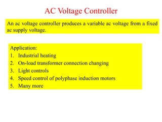
- 2. AC Voltage Controller An ac voltage controller produces a variable ac voltage from a fixed ac supply voltage. Application: 1. Industrial heating 2. On-load transformer connection changing 3. Light controls 4. Speed control of polyphase induction motors 5. Many more
- 4. OnŌĆōoff Control Fig. 1: Single phase AC voltage controller.
- 7. Single-phase Half-wave Controller Vm Vm Vm/R Žēt ŽĆ 2ŽĆ 0 Žēt vo ŽĆ 2ŽĆ 0 2ŽĆ Žēt vs ŽĆ 0 Žēt 0 vg1k ╬▒ ╬▒ ╬▒ Žēt ŽĆ 2ŽĆ 0 io vSW Fig. 2: Single-phase half-wave controller.
- 9. Single-phase Full-wave Controller Vm Vm Vm/R Žēt ŽĆ 2ŽĆ 0 Žēt vo ŽĆ 2ŽĆ 0 2ŽĆ Žēt vs ŽĆ 0 Žēt 0 vg1k ╬▒ ╬▒ ╬▒ Žēt ŽĆ 2ŽĆ 0 io vSW Fig. 3: Single-phase full-wave controller. Žēt 0 vg2k ŽĆ+╬▒
- 11. Single-phase Full-wave Controller Vm Vm Vm/R Žēt ŽĆ 2ŽĆ 0 Žēt vo ŽĆ 2ŽĆ 0 2ŽĆ Žēt vs ŽĆ 0 Žēt 0 vg1k ╬▒ ╬▒ ╬▒ io Fig. 4: Single-phase full-wave controller. ŽĆ+╬▒
- 12. Single-phase Full-wave Controller Vm Vm Žēt ŽĆ 2ŽĆ 0 Žēt vo ŽĆ 2ŽĆ 0 2ŽĆ Žēt vs ŽĆ 0 Žēt 0 vg1k ╬▒ ╬▒ Žēt ŽĆ 2ŽĆ 0 io vSW Fig. 5: Single-phase full-wave controller with RL load. Žēt 0 vg2k ŽĆ+╬▒ ╬▓ Žēt ŽĆ 2ŽĆ 0 vL
- 13. Three-phase Full-wave Controller Fig. 6: Three-phase full-wave controller.
- 14. Three-phase Full-wave Controller vi Žēt vcn ╬▒ 2ŽĆ Vm/2 0 Žēt Žēt 2ŽĆ vab vbc vca 0 0 vac vba vcb vcb Žēt 0 14 vbn van vab vac vbc vba vca vcb T1 T1 T4 T4 T3 T3 T6 T6 T5 T5 T2 T2 ŽĆ/3+╬▒ 2ŽĆ/3+╬▒ 4ŽĆ/3+╬▒ ŽĆ+╬▒ ŽĆ+╬▒ 4ŽĆ/3+╬▒ Firing Sequence T1= T2= T3= T4= ŽĆ T5= T6= Fig. : Input-output waveform of three-phase full-wave controller with R load for ╬▒=ŽĆ/3 (ŽĆ/3Ōēż╬▒<ŽĆ/2).
- 15. Three-phase Full-wave Controller vi Žēt vcn ╬▒ 2ŽĆ 0 Žēt Žēt 2ŽĆ vab vbc vca 0 0 vac vba vcb vcb Žēt 0 15 vbn van vab vac vbc vba vca vcb T1 T1 T4 T4 T3 T3 T6 T6 T5 T5 T2 T2 ŽĆ/3+╬▒ 2ŽĆ/3+╬▒ 4ŽĆ/3+╬▒ ŽĆ+╬▒ ŽĆ+╬▒ Firing Sequence T1= , T2= , T3= , ŽĆ T4= ŽĆ, T5= , T6= , 2ŽĆ Fig. : Input-output waveform of three-phase full-wave controller with R load for ╬▒=ŽĆ/2. vca 4ŽĆ/3+╬▒
- 16. Three-phase Full-wave Controller vi Žēt vcn ╬▒ 2ŽĆ 0 Žēt Žēt 2ŽĆ vab vbc vca 0 0 vac vba vcb vcb Žēt 0 16 vbn van vab vac vbc vba vcb T1 T1 T4 T4 T3 T3 T6 T6 T5 T5 T2 T2 ŽĆ/3+╬▒ 2ŽĆ/3+╬▒ ŽĆ+╬▒ ŽĆ+╬▒ Firing Sequence T1= , T2= , T3= , ŽĆ T4= ŽĆ, T5= , T6= , 2ŽĆ Fig. : Input-output waveform of three-phase full-wave controller with R load for ╬▒=2ŽĆ/3 (ŽĆ/2<╬▒<5ŽĆ/6).. vca
- 17. Thank You