


More Related Content
Similar to bridge anderson and desauty bridge emi.ppt (20)
More from ChandraPrakash715640 (10)


Recently uploaded (20)


bridge anderson and desauty bridge emi.ppt
- 1. GOVERNMENT POLYTECHNIC GULZARBAGH PATNA 7 By Prof. Chandra Prakash ELECTRONICS MEASUREMENT AND INSTRUMENTATION TOPICS COVERED ŌĆóAnderson Bridge ŌĆóDe-SautyŌĆÖs Bridge
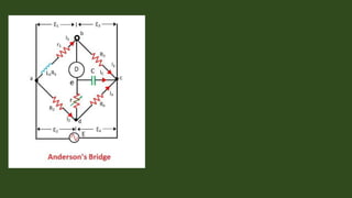
- 2. ANDERSON BRIDGES ŌĆó The AndersonŌĆÖs bridge gives the accurate measurement of self-inductance of the circuit. The bridge is the advanced form of MaxwellŌĆÖs inductance capacitance bridge. In Anderson bridge, the unknown inductance is compared with the standard fixed capacitance which is connected between the two arms of the bridge.
- 3. Construction of Anderson Bridge The bridge has fours arms ab, bc, cd, and ad. The arm ab consists unknown inductance along with the resistance. And the other three arms consist the purely resistive arms connected in series with the circuit.The static capacitor and the variable resistor are connected in series and placed in parallel with the cd arm. The voltage source is applied to the terminal a and c.
- 4. .
- 5. Theory of Anderson Bridge Let, L1 ŌĆō unknown inductance having a resistance R1. R2, R3, R4 ŌĆō known non-inductive resistance C4 ŌĆō standard capacitor At balance Condition, Now,
- 6. The other balance condition equation is expressed as By substituting the value of Ic in the above equation we get,
- 7. on equating the equation, we get Equating the real and the imaginary part, we get
- 8. Advantages of AndersonŌĆÖs Bridge: 1) In AndersonŌĆÖs bridge it is very easy to obtain the balance point as compared to MaxwellŌĆÖs bridge. 2) In this bridge a fixed standard capacitor is used therefore there is no need of costly variable capacitor. 3) This method is very accurate for measurement of capacitance in terms of inductance. Disadvantages of AndersonŌĆÖs Bridge: 1)It is more complex as compared with MaxwellŌĆÖs inductance bridge. It has more parts and hence complex in set up and manipulate. The balance equations of AndersonŌĆÖs bridge are quite complex and much more tedious. 2) The bridge has an additional junction which arises the difficulty in shielding the bridge.
- 9. Hay's bridge for high Q-factor (Q>10) inductance measurement, Maxwell's bridge for medium Q-factor (1<Q<10) inductance measurement and Anderson's bridge for low inductance (upto millihenry) measurements. But, won't it be more convenient if we can have a single bridge which can measure value of inductance over a wide range ? This is exactly what an Owen bridge does ŌĆō Measure inductance over a wide range.
- 10. De-SautyŌĆÖs Bridge Desauty's bridge is the simplest ac bridge circuit used for the measurement of unknown capacitance. The bridge gives a fair degree of accuracy for measuring capacitance over a wide range. It can be also used for comparing two capacitance.
- 11. Construction of De-sauty's Bridge The bridge consists of four branches or arms. Two capacitors C1 and C2 are placed in branches AB and AD respectively. The branches BC and CD consist of resistors R3 and R4 respectively. An ac source is connected between terminals A and C. The circuit diagram of the bridge is shown in the figure. A null indicator is connected across terminals B and D, which indicates null deflection when the bridge is balanced.
- 13. Let, ŌĆóC1 = Unknown capacitance ŌĆóC2 = Known standard capacitance ŌĆóR3 = Known standard non-inductive resistance ŌĆóR4 = Known standard non-inductive resistance. From the above figure, the impedances in each arm is given as
- 14. When the bridge is balanced, we have, It is the easiest method for the measurement of capacitance as it has a simple circuit and only one variable element. In order to bring the bridge into a balanced condition, either R3 or R4 can be chosen as a variable element.
- 15. Advantages of the De-SautyŌĆÖs Bridges 1.The advantage of this bridge is its simplicity to obtain a perfect balance. 2.The calculations are very easy Disadvantages of the De-SautyŌĆÖs Bridge 1.If both capacitors are not free from dielectric loss then it is not possible to obtain the balance condition. This method therefore used only for air capacitor, which are more or less loss free.
- 16. Schering bridge The Schering bridge use for measuring the capacitance of the capacitor, dissipation factor, properties of an insulator, capacitor bushing, insulating oil and other insulating materials. It is one of the most commonly used AC bridge. The Schering bridge works on the principle of balancing the load on its arm. WienŌĆÖs bridge The WienŌĆÖs bridge use in AC circuits for determining the value of unknown frequency. The bridge measures the frequencies from 100Hz to 100kHz. The accuracy of the bridges lies between 0.1 to 0.5 percent. The bridge is used for various other applications like capacitance measurement, harmonic distortion analyser and in the HF frequency oscillator.