
Combinational Circuits encoders and decoders
- 1. COE 202: Digital Logic Design Combinational Circuits Part 3 KFUPM Courtesy of Dr. Ahmad Almulhem
- 2. Objectives ŌĆó Decoders ŌĆó Encoders ŌĆó Multiplexers ŌĆó DeMultiplexers KFUPM
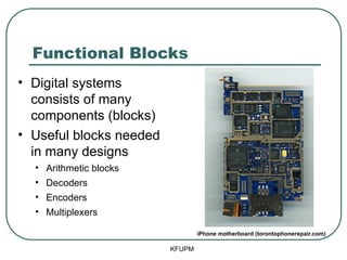
- 3. Functional Blocks ŌĆó Digital systems consists of many components (blocks) ŌĆó Useful blocks needed in many designs ŌĆó Arithmetic blocks ŌĆó Decoders ŌĆó Encoders ŌĆó Multiplexers KFUPM iPhone motherboard (torontophonerepair.com)
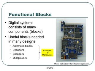
- 4. Functional Blocks ŌĆó Digital systems consists of many components (blocks) ŌĆó Useful blocks needed in many designs ŌĆó Arithmetic blocks ŌĆó Decoders ŌĆó Encoders ŌĆó Multiplexers KFUPM iPhone motherboard (torontophonerepair.com) Examples of MSI devices
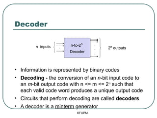
- 5. Decoder ŌĆó Information is represented by binary codes ŌĆó Decoding - the conversion of an n-bit input code to an m-bit output code with n <= m <= 2n such that each valid code word produces a unique output code ŌĆó Circuits that perform decoding are called decoders ŌĆó A decoder is a minterm generator KFUPM . . . . n inputs 2n outputs n-to-2n Decoder
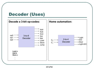
- 6. Decoder (Uses) Decode a 3-bit op-codes: Home automation: KFUPM 3-to-8 Decoder Add Sub And Xor Not Load Store Jump op0 op1 op2 2-to-4 Decoder Light A/C Door Light-A/C C0 C1 Load a Add b Store c . .
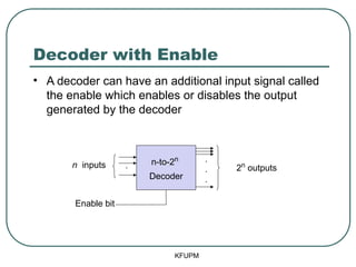
- 7. Decoder with Enable KFUPM ŌĆó A decoder can have an additional input signal called the enable which enables or disables the output generated by the decoder . . . 2n outputs n-to-2n Decoder Enable bit . n inputs
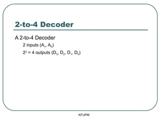
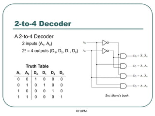
- 8. 2-to-4 Decoder A 2-to-4 Decoder 2 inputs (A1, A0) 22 = 4 outputs (D3, D2, D1, D0) KFUPM
- 9. 2-to-4 Decoder A 2-to-4 Decoder 2 inputs (A1, A0) 22 = 4 outputs (D3, D2, D1, D0) Truth Table A1 A0 D0 D1 D2 D3 0 0 1 0 0 0 0 1 0 1 0 0 1 0 0 0 1 0 1 1 0 0 0 1 KFUPM
- 10. 2-to-4 Decoder A 2-to-4 Decoder 2 inputs (A1, A0) 22 = 4 outputs (D3, D2, D1, D0) Truth Table A1 A0 D0 D1 D2 D3 0 0 1 0 0 0 0 1 0 1 0 0 1 0 0 0 1 0 1 1 0 0 0 1 Src: ManoŌĆÖs book KFUPM
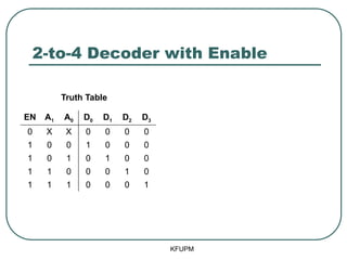
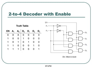
- 11. 2-to-4 Decoder with Enable KFUPM EN A1 A0 D0 D1 D2 D3 0 X X 0 0 0 0 1 0 0 1 0 0 0 1 0 1 0 1 0 0 1 1 0 0 0 1 0 1 1 1 0 0 0 1 Truth Table
- 12. 2-to-4 Decoder with Enable KFUPM EN A1 A0 D0 D1 D2 D3 0 X X 0 0 0 0 1 0 0 1 0 0 0 1 0 1 0 1 0 0 1 1 0 0 0 1 0 1 1 1 0 0 0 1 Src: ManoŌĆÖs book Truth Table
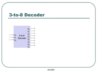
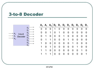
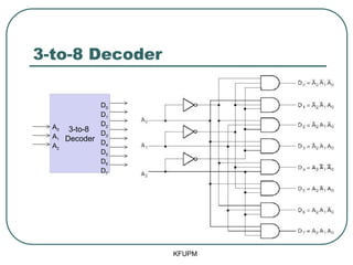
- 14. 3-to-8 Decoder KFUPM A2 A1 A0 D0 D1 D2 D3 D4 D5 D6 D7 0 0 0 1 0 0 0 0 0 0 0 0 0 1 0 1 0 0 0 0 0 0 0 1 0 0 0 1 0 0 0 0 0 0 1 1 0 0 0 1 0 0 0 0 1 0 0 0 0 0 0 1 0 0 0 1 0 1 0 0 0 0 0 1 0 0 1 1 0 0 0 0 0 0 0 1 0 1 1 1 0 0 0 0 0 0 0 1 3-to-8 Decoder D0 D1 D2 D3 D4 D5 D6 D7 A0 A1 A2
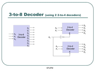
- 16. 3-to-8 Decoder (using 2 2-to-4 decoders) KFUPM 3-to-8 Decoder 2-to-4 Decoder D0 D1 D2 D3 D4 D5 D6 D7 A0 A1 A2 2-to-4 Decoder D0 D1 D2 D3 D4 D5 D6 D7 A0 A1 A0 A1 A2 E E
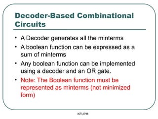
- 17. Decoder-Based Combinational Circuits ŌĆó A Decoder generates all the minterms ŌĆó A boolean function can be expressed as a sum of minterms ŌĆó Any boolean function can be implemented using a decoder and an OR gate. ŌĆó Note: The Boolean function must be represented as minterms (not minimized form) KFUPM
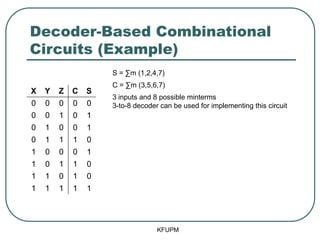
- 18. Decoder-Based Combinational Circuits (Example) KFUPM X Y Z C S 0 0 0 0 0 0 0 1 0 1 0 1 0 0 1 0 1 1 1 0 1 0 0 0 1 1 0 1 1 0 1 1 0 1 0 1 1 1 1 1 S = Ōłæm (1,2,4,7) C = Ōłæm (3,5,6,7) 3 inputs and 8 possible minterms 3-to-8 decoder can be used for implementing this circuit
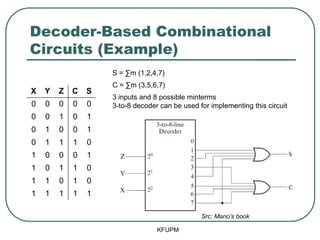
- 19. Decoder-Based Combinational Circuits (Example) KFUPM Src: ManoŌĆÖs book X Y Z C S 0 0 0 0 0 0 0 1 0 1 0 1 0 0 1 0 1 1 1 0 1 0 0 0 1 1 0 1 1 0 1 1 0 1 0 1 1 1 1 1 S = Ōłæm (1,2,4,7) C = Ōłæm (3,5,6,7) 3 inputs and 8 possible minterms 3-to-8 decoder can be used for implementing this circuit
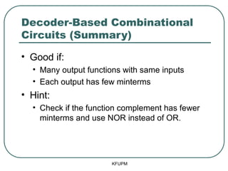
- 20. Decoder-Based Combinational Circuits (Summary) ŌĆó Good if: ŌĆó Many output functions with same inputs ŌĆó Each output has few minterms ŌĆó Hint: ŌĆó Check if the function complement has fewer minterms and use NOR instead of OR. KFUPM
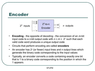
- 21. Encoder ŌĆó Encoding - the opposite of decoding - the conversion of an m-bit input code to a n-bit output code with n ┬Ż m ┬Ż 2n such that each valid code word produces a unique output code ŌĆó Circuits that perform encoding are called encoders ŌĆó An encoder has 2n (or fewer) input lines and n output lines which generate the binary code corresponding to the input values ŌĆó Typically, an encoder converts a code containing exactly one bit that is 1 to a binary code corresponding to the position in which the 1 appears. . . . . n outputs 2n inputs 2n -to-n Encoder KFUPM
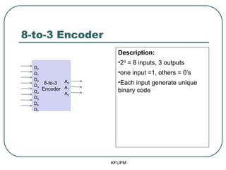
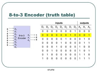
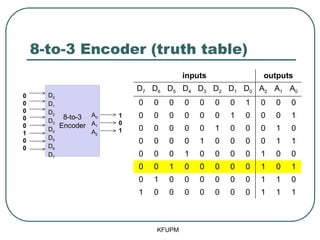
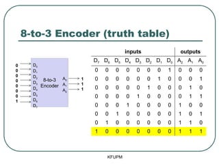
- 22. 8-to-3 Encoder Description: ŌĆó23 = 8 inputs, 3 outputs ŌĆóone input =1, others = 0ŌĆÖs ŌĆóEach input generate unique binary code KFUPM 8-to-3 Encoder D0 D1 D2 D3 D4 D5 D6 D7 A0 A1 A2
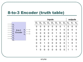
- 23. 8-to-3 Encoder (truth table) KFUPM 8-to-3 Encoder D0 D1 D2 D3 D4 D5 D6 D7 A0 A1 A2 inputs outputs D7 D6 D5 D4 D3 D2 D1 D0 A2 A1 A0 0 0 0 0 0 0 0 1 0 0 0 0 0 0 0 0 0 1 0 0 0 1 0 0 0 0 0 1 0 0 0 1 0 0 0 0 0 1 0 0 0 0 1 1 0 0 0 1 0 0 0 0 1 0 0 0 0 1 0 0 0 0 0 1 0 1 0 1 0 0 0 0 0 0 1 1 0 1 0 0 0 0 0 0 0 1 1 1
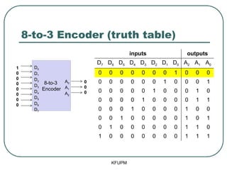
- 24. 8-to-3 Encoder (truth table) KFUPM 8-to-3 Encoder D0 D1 D2 D3 D4 D5 D6 D7 A0 A1 A2 1 0 0 0 0 0 0 0 0 0 0 inputs outputs D7 D6 D5 D4 D3 D2 D1 D0 A2 A1 A0 0 0 0 0 0 0 0 1 0 0 0 0 0 0 0 0 0 1 0 0 0 1 0 0 0 0 0 1 0 0 0 1 0 0 0 0 0 1 0 0 0 0 1 1 0 0 0 1 0 0 0 0 1 0 0 0 0 1 0 0 0 0 0 1 0 1 0 1 0 0 0 0 0 0 1 1 0 1 0 0 0 0 0 0 0 1 1 1
- 25. 8-to-3 Encoder (truth table) KFUPM 8-to-3 Encoder D0 D1 D2 D3 D4 D5 D6 D7 A0 A1 A2 0 1 0 0 0 0 0 0 1 0 0 inputs outputs D7 D6 D5 D4 D3 D2 D1 D0 A2 A1 A0 0 0 0 0 0 0 0 1 0 0 0 0 0 0 0 0 0 1 0 0 0 1 0 0 0 0 0 1 0 0 0 1 0 0 0 0 0 1 0 0 0 0 1 1 0 0 0 1 0 0 0 0 1 0 0 0 0 1 0 0 0 0 0 1 0 1 0 1 0 0 0 0 0 0 1 1 0 1 0 0 0 0 0 0 0 1 1 1
- 26. 8-to-3 Encoder (truth table) KFUPM 8-to-3 Encoder D0 D1 D2 D3 D4 D5 D6 D7 A0 A1 A2 0 0 0 0 0 1 0 0 1 0 1 inputs outputs D7 D6 D5 D4 D3 D2 D1 D0 A2 A1 A0 0 0 0 0 0 0 0 1 0 0 0 0 0 0 0 0 0 1 0 0 0 1 0 0 0 0 0 1 0 0 0 1 0 0 0 0 0 1 0 0 0 0 1 1 0 0 0 1 0 0 0 0 1 0 0 0 0 1 0 0 0 0 0 1 0 1 0 1 0 0 0 0 0 0 1 1 0 1 0 0 0 0 0 0 0 1 1 1
- 27. 8-to-3 Encoder (truth table) KFUPM 8-to-3 Encoder D0 D1 D2 D3 D4 D5 D6 D7 A0 A1 A2 0 0 0 0 0 0 0 1 1 1 1 inputs outputs D7 D6 D5 D4 D3 D2 D1 D0 A2 A1 A0 0 0 0 0 0 0 0 1 0 0 0 0 0 0 0 0 0 1 0 0 0 1 0 0 0 0 0 1 0 0 0 1 0 0 0 0 0 1 0 0 0 0 1 1 0 0 0 1 0 0 0 0 1 0 0 0 0 1 0 0 0 0 0 1 0 1 0 1 0 0 0 0 0 0 1 1 0 1 0 0 0 0 0 0 0 1 1 1
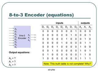
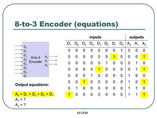
- 28. 8-to-3 Encoder (equations) KFUPM 8-to-3 Encoder D0 D1 D2 D3 D4 D5 D6 D7 A0 A1 A2 inputs outputs D7 D6 D5 D4 D3 D2 D1 D0 A2 A1 A0 0 0 0 0 0 0 0 1 0 0 0 0 0 0 0 0 0 1 0 0 0 1 0 0 0 0 0 1 0 0 0 1 0 0 0 0 0 1 0 0 0 0 1 1 0 0 0 1 0 0 0 0 1 0 0 0 0 1 0 0 0 0 0 1 0 1 0 1 0 0 0 0 0 0 1 1 0 1 0 0 0 0 0 0 0 1 1 1 Note: This truth table is not complete! Why? Output equations: A0 = ? A1 = ? A2 = ?
- 29. 8-to-3 Encoder (equations) KFUPM 8-to-3 Encoder D0 D1 D2 D3 D4 D5 D6 D7 A0 A1 A2 inputs outputs D7 D6 D5 D4 D3 D2 D1 D0 A2 A1 A0 0 0 0 0 0 0 0 1 0 0 0 0 0 0 0 0 0 1 0 0 0 1 0 0 0 0 0 1 0 0 0 1 0 0 0 0 0 1 0 0 0 0 1 1 0 0 0 1 0 0 0 0 1 0 0 0 0 1 0 0 0 0 0 1 0 1 0 1 0 0 0 0 0 0 1 1 0 1 0 0 0 0 0 0 0 1 1 1 Output equations: A0 = D1 + D3 + D5 + D7 A1 = ? A2 = ?
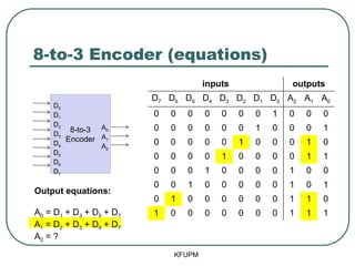
- 30. 8-to-3 Encoder (equations) KFUPM 8-to-3 Encoder D0 D1 D2 D3 D4 D5 D6 D7 A0 A1 A2 inputs outputs D7 D6 D5 D4 D3 D2 D1 D0 A2 A1 A0 0 0 0 0 0 0 0 1 0 0 0 0 0 0 0 0 0 1 0 0 0 1 0 0 0 0 0 1 0 0 0 1 0 0 0 0 0 1 0 0 0 0 1 1 0 0 0 1 0 0 0 0 1 0 0 0 0 1 0 0 0 0 0 1 0 1 0 1 0 0 0 0 0 0 1 1 0 1 0 0 0 0 0 0 0 1 1 1 Output equations: A0 = D1 + D3 + D5 + D7 A1 = D2 + D3 + D6 + D7 A2 = ?
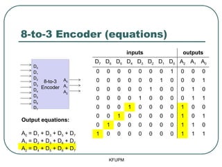
- 31. 8-to-3 Encoder (equations) KFUPM 8-to-3 Encoder D0 D1 D2 D3 D4 D5 D6 D7 A0 A1 A2 inputs outputs D7 D6 D5 D4 D3 D2 D1 D0 A2 A1 A0 0 0 0 0 0 0 0 1 0 0 0 0 0 0 0 0 0 1 0 0 0 1 0 0 0 0 0 1 0 0 0 1 0 0 0 0 0 1 0 0 0 0 1 1 0 0 0 1 0 0 0 0 1 0 0 0 0 1 0 0 0 0 0 1 0 1 0 1 0 0 0 0 0 0 1 1 0 1 0 0 0 0 0 0 0 1 1 1 Output equations: A0 = D1 + D3 + D5 + D7 A1 = D2 + D3 + D6 + D7 A2 = D4 + D5 + D6 + D7
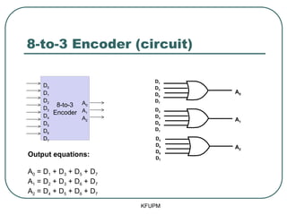
- 32. 8-to-3 Encoder (circuit) KFUPM 8-to-3 Encoder D0 D1 D2 D3 D4 D5 D6 D7 A0 A1 A2 Output equations: A0 = D1 + D3 + D5 + D7 A1 = D2 + D3 + D6 + D7 A2 = D4 + D5 + D6 + D7 A0 A1 A2 D1 D3 D5 D7 D2 D3 D6 D7 D4 D5 D6 D7
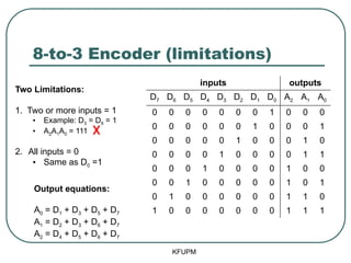
- 33. 8-to-3 Encoder (limitations) KFUPM Output equations: A0 = D1 + D3 + D5 + D7 A1 = D2 + D3 + D6 + D7 A2 = D4 + D5 + D6 + D7 inputs outputs D7 D6 D5 D4 D3 D2 D1 D0 A2 A1 A0 0 0 0 0 0 0 0 1 0 0 0 0 0 0 0 0 0 1 0 0 0 1 0 0 0 0 0 1 0 0 0 1 0 0 0 0 0 1 0 0 0 0 1 1 0 0 0 1 0 0 0 0 1 0 0 0 0 1 0 0 0 0 0 1 0 1 0 1 0 0 0 0 0 0 1 1 0 1 0 0 0 0 0 0 0 1 1 1 Two Limitations: 1. Two or more inputs = 1 ŌĆó Example: D3 = D6 = 1 ŌĆó A2A1A0 = 111 2. All inputs = 0 ŌĆó Same as D0 =1
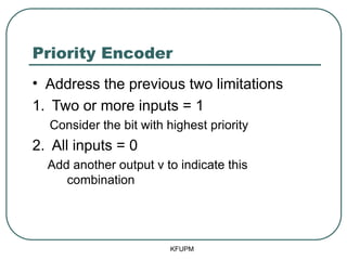
- 34. Priority Encoder ŌĆó Address the previous two limitations 1. Two or more inputs = 1 Consider the bit with highest priority 2. All inputs = 0 Add another output v to indicate this combination KFUPM
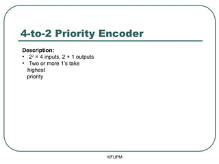
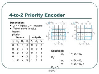
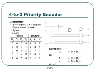
- 35. 4-to-2 Priority Encoder KFUPM Description: ŌĆó 22 = 4 inputs, 2 + 1 outputs ŌĆó Two or more 1ŌĆÖs take highest priority
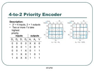
- 36. 4-to-2 Priority Encoder KFUPM inputs outputs D3 D2 D1 D0 A1 A0 V 0 0 0 0 X X 0 0 0 0 1 0 0 1 0 0 1 X 0 1 1 0 1 X X 1 0 1 1 X X X 1 1 1 Description: ŌĆó 22 = 4 inputs, 2 + 1 outputs ŌĆó Two or more 1ŌĆÖs take highest priority This is a condensed truth table! It has only 5 rows instead of 16! Row 3 = 2 combinations Row 4 = 4 combinations Row 5 = 8 combinations
- 37. 4-to-2 Priority Encoder KFUPM inputs outputs D3 D2 D1 D0 A1 A0 V 0 0 0 0 X X 0 0 0 0 1 0 0 1 0 0 1 X 0 1 1 0 1 X X 1 0 1 1 X X X 1 1 1 Description: ŌĆó 22 = 4 inputs, 2 + 1 outputs ŌĆó Two or more 1ŌĆÖs take highest priority
- 38. 4-to-2 Priority Encoder KFUPM inputs outputs D3 D2 D1 D0 A1 A0 V 0 0 0 0 X X 0 0 0 0 1 0 0 1 0 0 1 X 0 1 1 0 1 X X 1 0 1 1 X X X 1 1 1 Description: ŌĆó 22 = 4 inputs, 2 + 1 outputs ŌĆó Two or more 1ŌĆÖs take highest priority Equations: A0 = D3 + D1 D2ŌĆÖ A1 = D2 + D3 V = D0 + D1 + D2 + D3
- 39. 4-to-2 Priority Encoder KFUPM inputs outputs D3 D2 D1 D0 A1 A0 V 0 0 0 0 X X 0 0 0 0 1 0 0 1 0 0 1 X 0 1 1 0 1 X X 1 0 1 1 X X X 1 1 1 Description: ŌĆó 22 = 4 inputs, 2 + 1 outputs ŌĆó Two or more 1ŌĆÖs take highest priority Equations: A0 = D3 + D1 D2ŌĆÖ A1 = D2 + D3 V = D0 + D1 + D2 + D3
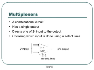
- 40. Multiplexers ŌĆó A combinational circuit ŌĆó Has a single output ŌĆó Directs one of 2n input to the output ŌĆó Choosing which input is done using n select lines KFUPM 2n inputs n select lines one output 2n x 1 MUX
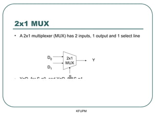
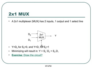
- 41. 2x1 MUX ŌĆó A 2x1 multiplexer (MUX) has 2 inputs, 1 output and 1 select line ŌĆó Y=D0 for S0=0, and Y=D1 for S0=1 ŌĆó Minimizing will result in: Y = S0ŌĆÖ.D0 + S0.D1 ŌĆó Exercise: Draw the circuit? KFUPM S0 D0 D1 Y 2x1 MUX
- 42. 2x1 MUX ŌĆó A 2x1 multiplexer (MUX) has 2 inputs, 1 output and 1 select line ŌĆó Y=D0 for S0=0, and Y=D1 for S0=1 ŌĆó Minimizing will result in: Y = S0ŌĆÖ.D0 + S0.D1 ŌĆó Exercise: Draw the circuit? KFUPM S0 D0 D1 Y 2x1 MUX
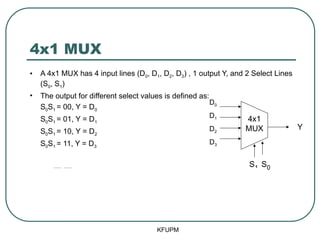
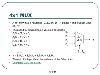
- 43. 4x1 MUX ŌĆó A 4x1 MUX has 4 input lines (D0, D1, D2, D3) , 1 output Y, and 2 Select Lines (S0, S1) ŌĆó The output for different select values is defined as: S0S1 = 00, Y = D0 S0S1 = 01, Y = D1 S0S1 = 10, Y = D2 S0S1 = 11, Y = D3 ŌĆó Y = S1S0D0 + S1S0D1 + S1S0D2 + S1S0D3 ŌĆó The output Y depends on the minterms of the Select lines ŌĆó Exercise: Draw the circuit? KFUPM S1 S0 D0 D1 D2 D3 Y 4x1 MUX
- 44. 4x1 MUX ŌĆó A 4x1 MUX has 4 input lines (D0, D1, D2, D3) , 1 output Y, and 2 Select Lines (S0, S1) ŌĆó The output for different select values is defined as: S0S1 = 00, Y = D0 S0S1 = 01, Y = D1 S0S1 = 10, Y = D2 S0S1 = 11, Y = D3 ŌĆó Y = S1S0D0 + S1S0D1 + S1S0D2 + S1S0D3 ŌĆó The output Y depends on the minterms of the Select lines ŌĆó Exercise: Draw the circuit? KFUPM S1 S0 D0 D1 D2 D3 Y 4x1 MUX
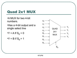
- 45. Quad 2x1 MUX ŌĆóA MUX for two 4-bit numbers. ŌĆóHas a 4-bit output and a single select line ŌĆóY = A If S0 = 0 ŌĆóY = B if S0 = 1 KFUPM S0 A0 A1 A2 A3 B0 B1 B2 B3 Y0 Y1 Y2 Y3 QUAD 2X1 MUX
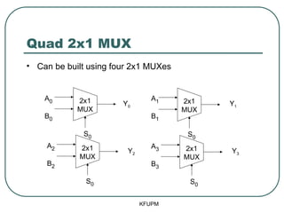
- 46. Quad 2x1 MUX ŌĆó Can be built using four 2x1 MUXes KFUPM S0 A0 B0 Y0 2x1 MUX S0 A2 B2 Y2 2x1 MUX S0 A1 B1 Y1 2x1 MUX S0 A3 B3 Y3 2x1 MUX
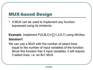
- 47. MUX-based Design ŌĆó A MUX can be used to implement any function expressed using its minterms Example: Implement F(A,B,C)=Ōłæ(1,2,6,7) using MUXes Solution1: We can use a MUX with the number of select lines equal to the number of input variables of the function. Since this function has 3 input variables, it will require 3 select lines, i.e. an 8x1 MUX KFUPM
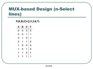
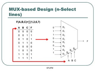
- 48. MUX-based Design (n-Select lines) KFUPM F(A,B,C)=Ōłæ(1,2,6,7) A B C F 0 0 0 0 0 0 1 1 0 1 0 1 0 1 1 0 1 0 0 0 1 0 1 0 1 1 0 1 1 1 1 1
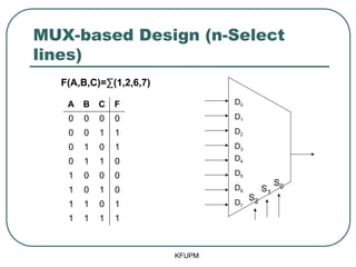
- 49. MUX-based Design (n-Select lines) KFUPM D0 D1 D2 D3 D4 D5 D6 D7 S0 S2 S1 F(A,B,C)=Ōłæ(1,2,6,7) A B C F 0 0 0 0 0 0 1 1 0 1 0 1 0 1 1 0 1 0 0 0 1 0 1 0 1 1 0 1 1 1 1 1
- 50. MUX-based Design (n-Select lines) KFUPM D0 D1 D2 D3 D4 D5 D6 D7 F 0 1 1 0 0 0 1 1 S0 S2 S1 A B C F(A,B,C)=Ōłæ(1,2,6,7) A B C F 0 0 0 0 0 0 1 1 0 1 0 1 0 1 1 0 1 0 0 0 1 0 1 0 1 1 0 1 1 1 1 1
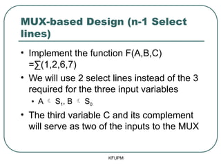
- 51. MUX-based Design (n-1 Select lines) ŌĆó Implement the function F(A,B,C) =Ōłæ(1,2,6,7) ŌĆó We will use 2 select lines instead of the 3 required for the three input variables ŌĆó A ’āĀ S1, B ’āĀ S0 ŌĆó The third variable C and its complement will serve as two of the inputs to the MUX KFUPM
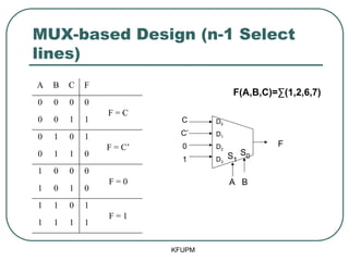
- 52. MUX-based Design (n-1 Select lines) KFUPM A B C F 0 0 0 0 F = C 0 0 1 1 0 1 0 1 F = CŌĆÖ 0 1 1 0 1 0 0 0 F = 0 1 0 1 0 1 1 0 1 F = 1 1 1 1 1 D0 D1 D2 D3 F S1 S0 A B C CŌĆÖ 0 1 F(A,B,C)=Ōłæ(1,2,6,7)
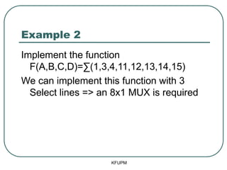
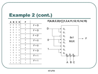
- 53. Example 2 Implement the function F(A,B,C,D)=Ōłæ(1,3,4,11,12,13,14,15) We can implement this function with 3 Select lines => an 8x1 MUX is required KFUPM
- 54. Example 2 (cont.) KFUPM A B C D F 0 0 0 0 0 F = D 0 0 0 1 1 0 0 1 0 0 F = D 0 0 1 1 1 0 1 0 0 1 F = DŌĆÖ 0 1 0 1 0 0 1 1 0 0 F = 0 0 1 1 1 0 1 0 0 0 0 F = 0 1 0 0 1 0 1 0 1 0 0 F = D 1 0 1 1 1 1 1 0 0 1 F = 1 1 1 0 1 1 1 1 1 0 1 F = 1 1 1 1 1 1 D0 D1 D2 D3 D4 D5 D6 D7 D 0 1 8x1 MUX F A B C S2 S1 S0 F(A,B,C,D)=Ōłæ(1,3,4,11,12,13,14,15)
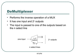
- 55. DeMultiplexer ŌĆó Performs the inverse operation of a MUX ŌĆó It has one input and 2n outputs ŌĆó The input is passed to one of the outputs based on the n select line KFUPM 2n outputs n select lines one input 1 x 2n DeMUX
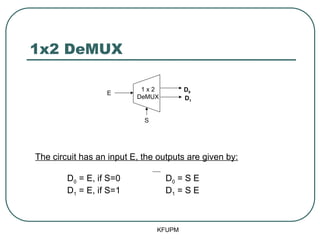
- 56. 1x2 DeMUX KFUPM The circuit has an input E, the outputs are given by: D0 = E, if S=0 D0 = S E D1 = E, if S=1 D1 = S E S E 1 x 2 DeMUX D0 D1
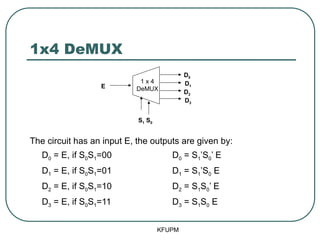
- 57. 1x4 DeMUX The circuit has an input E, the outputs are given by: D0 = E, if S0S1=00 D0 = S1ŌĆÖS0ŌĆÖ E D1 = E, if S0S1=01 D1 = S1ŌĆÖS0 E D2 = E, if S0S1=10 D2 = S1S0ŌĆÖ E D3 = E, if S0S1=11 D3 = S1S0 E KFUPM E S1 S0 D0 D1 D2 D3 1 x 4 DeMUX
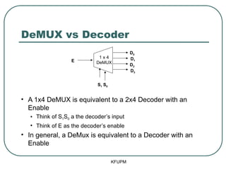
- 58. DeMUX vs Decoder ŌĆó A 1x4 DeMUX is equivalent to a 2x4 Decoder with an Enable ŌĆó Think of S1S0 a the decoderŌĆÖs input ŌĆó Think of E as the decoderŌĆÖs enable ŌĆó In general, a DeMux is equivalent to a Decoder with an Enable KFUPM E D0 D1 D2 D3 1 x 4 DeMUX S1 S0
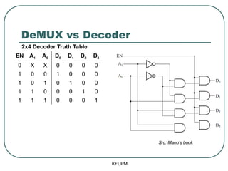
- 59. DeMUX vs Decoder KFUPM EN A1 A0 D0 D1 D2 D3 0 X X 0 0 0 0 1 0 0 1 0 0 0 1 0 1 0 1 0 0 1 1 0 0 0 1 0 1 1 1 0 0 0 1 Src: ManoŌĆÖs book 2x4 Decoder Truth Table
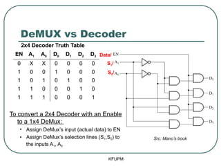
- 60. DeMUX vs Decoder KFUPM EN A1 A0 D0 D1 D2 D3 0 X X 0 0 0 0 1 0 0 1 0 0 0 1 0 1 0 1 0 0 1 1 0 0 0 1 0 1 1 1 0 0 0 1 Src: ManoŌĆÖs book 2x4 Decoder Truth Table To convert a 2x4 Decoder with an Enable to a 1x4 DeMux: ŌĆó Assign DeMuxŌĆÖs input (actual data) to EN ŌĆó Assign DeMuxŌĆÖs selection lines (S1,S0) to the inputs A1, A0 Data/ S1/ S0/
- 61. Summary ŌĆó Useful Functional Blocks ŌĆó Decoders ŌĆó Encoders ŌĆó Multiplexers ŌĆó DeMultiplexers ŌĆó All are examples of MSI devices ŌĆó Can be used to build bigger systems KFUPM