ºÝºÝߣ

ºÝºÝߣShare a Scribd company logo
Case Study - Transient Analysis of a Power System
using EMTP-RV Software
UNIVERSITY OF SOUTHERN CALIFORNIA
Professor’s Name- Syed Ahmed
Subject- EE524 (Transients in Power System)
Name – Satwik Jain
USC ID- 1854593672
Email Id- satwikja@usc.edu
MS	in	Electrical	Engineering	(Electric	Power)	
	
Spring	
16	
/ Akshay Anand Nerurkar
/nerurkar@usc.edu
/8759392138
INTRODUCTION
	
Transient disturbances in power systems may damage key equipment, potentially having a great impact
on system reliability. These transients may be introduced during normal switching operations,
interruption of short circuits, lightning strikes, or due to equipment failure. Phasor analysis or other
simplified analysis methods are usually inadequate due to system frequency dependencies and
nonlinearities. Therefore, time-domain computer models are typically developed as a means of predicting
the severity of the transient occurrences. The simulations are typically performed using simulation
software such as the Electromagnetic Transient Program (EMTP). In this work, a royalty-free version of
EMTP is used.
Some of the cases are discussed below:
Capacitor	Bank	Switching:	
	
During the switching of shunt capacitor banks, high magnitude and high frequency transients can occur.
In earlier years, shunt capacitor banks have been more commonly installed at distribution and lower sub
transmission levels. However, there has been a recent proliferation of new capacitor banks at transmission
levels. Since larger higher-voltage capacitor banks have more stored energy and there is a higher system
X/R ratio and less damping, this has raised concerns at utilities (like Northern States Power Company)
regarding the vulnerability of their equipment.
Figure: Capacitor Bank Switching Main Design
When SW6 is closed at 15 ms and SW5 is closed at 20 ms. Following results were observed:
Figure: Transient Voltage across SW6
Figure: Transient voltages across SW5
The peak of the transients goes up to approx. 48k i.e. 1.5 times of the Rated voltage.
Figure: Inrush Current across CB near Generator
We can observe from above figure, the inrush current from the generator due to switching is almost 3 kA
that is really high to damage the circuit. Energization inrush is a transient occurring when the first (or
only) bank at the bus is energized. The transient is characterized by a surge of current having a high
magnitude and a frequency as high as several hundred Hertz. There is also a transient overvoltage on the
bus, caused by the surge of inrush current coming from the system source.
Figure: Current through SW5 (towards 2nd
capacitor)
Back-to-Back	Switching:	
	
Energizing the second bank C5 when the first bank C4 is already energized (already closed at steady
state) is called back-to- back switching, and is simulated by closing switch SW11 when C4 is already
operating in steady state. The resulting inrush to C5 is a high-frequency transient which primarily
involves the series combination of C4, L8, and C5, driven by the voltage V(0) on C4 at the instant SW11
is closed. Just as with energization of a single bank, worst case occurs when the bus voltage is at its
positive or negative peak value. This transient is typically in the kHz range.
Figure: Main design showing Back-to-Back Switching of capacitor bank
The following graphs were observed:
Figure: Current and Voltage observed across Main Circuit breaker (SW7) respectively
Figure: Inrush Current through Circuit breaker of C4 (SW12)
Figure: Back-to-Back Inrush current through circuit breaker SW11 when it is energized
Transformer	Switching	Transient:	
Transformer switching is the most commonly performed operation in any power delivery system and
most of the times this operation can be performed without any undesirable consequences. However, given
the right combination of system parameters, switching can result in a violent interaction between the
circuit breaker and the transformer.
This type of failures can best be explained by understanding as to how the switching induced transients
are produced and how the transformer windings react to them. Switching transients can be produced by
the breaker contact re-ignitions and / or by current chopping.
Figure: Main Design for Transformer Switching (during High Inductive Load)
Figure: High Inrush current through Circuit breaker 1
Figure: High Inrush current through Circuit breaker 2
This high magnitude of Inrush current may damage the windings of transformer. It may also cause
blasting of the transformer due to Insulation damage.
Figure : Voltage observed across Circuit breaker 1
Figure : Voltage observed across Circuit breaker 2
Controlled Switching can help to reduce the peaks (or eliminate) these high Inrush currents.
Transient	Recovery	Voltages:	
Figure: Main design to analysis Transient Recovery Voltages
In the above circuit, Switch 2 is closed at 10ms and opened at 20 ms, creating a ground fault for 10ms
period. The main Circuit breaker (SW1) is closed at steady state but is opened at 15ms.
We observe a High Transient Recovery across the Circuit breaker (SW1) during interruption of fault
current. This can be seen from below figure:
Figure: Transient Recovery voltages across SW1 during interruption of fault current
Figure: Fault current through SW1 during interruption
As we can observe from the above figure, the fault current interrupted by the Main circuit breaker (SW1)
is around 2.7 kA i.e. approx. 4.5 times of the rated current.
APPENDIX	
Transient Recovery Voltages: A transient recovery voltage (or TRV) for high-voltage Circuit Breakers
is the voltage that appears across the terminals after current interruption. It is a critical parameter of fault
interruption by a high-voltage circuit breaker; its characteristics (amplitude, rate of rise) can lead either to
a successful current interruption or to a failure (called re-ignition or restrike).
Circuit Parameters:
R1 = 0.5 Ohms; L5 = 3 mH; R4 = 0.001 Ohms; L6 = 12 mH
C4 = 40.1 uF (18 MVAR); C5 = 22.3 uF (10 MVAR) C6 = 601 uF
Dist. Transformer: 34.5/115 kV; R5 = 0.001 Ohms; L7 = 12 mH
Circuit Parameters:
Generators: 15kV; Transformers: 15/345 kV; Transmission Lines: 10 miles, R’ = 0.2687, L’ = 2.981, C’
= 36.933; C1= 1 uF; C2= 1 uF

More Related Content

What's hot (20)

Control of Active And reactive power flow in transmission line and power Osci...
Control of Active And reactive power flow in transmission line and power Osci...Control of Active And reactive power flow in transmission line and power Osci...
Control of Active And reactive power flow in transmission line and power Osci...
AM Publications
Ìý
Unit 2 Reactive Power Management
Unit 2 Reactive Power ManagementUnit 2 Reactive Power Management
Unit 2 Reactive Power Management
SANTOSH GADEKAR
Ìý
Voltage stability enhancement of a Transmission Line
Voltage stability  enhancement of a Transmission Line Voltage stability  enhancement of a Transmission Line
Voltage stability enhancement of a Transmission Line
anirudh sharma
Ìý
Unit 3 FACTS Technology
Unit 3 FACTS TechnologyUnit 3 FACTS Technology
Unit 3 FACTS Technology
SANTOSH GADEKAR
Ìý
Optimal Reactive Power Compensation in Electric Transmission Line using STATCOM
Optimal Reactive Power Compensation in Electric Transmission Line using STATCOMOptimal Reactive Power Compensation in Electric Transmission Line using STATCOM
Optimal Reactive Power Compensation in Electric Transmission Line using STATCOM
IOSR Journals
Ìý
Power System Analysis!
Power System Analysis!Power System Analysis!
Power System Analysis!
PRABHAHARAN429
Ìý
Per unit systems in power systems
Per unit systems in power systemsPer unit systems in power systems
Per unit systems in power systems
anoopeluvathingal
Ìý
Power control in power systems
Power control in power systemsPower control in power systems
Power control in power systems
Abhinash Yadav
Ìý
Traction Motors and Control
Traction Motors and ControlTraction Motors and Control
Traction Motors and Control
SANTOSH GADEKAR
Ìý
Control And Programingof Synchronous Generator
Control And Programingof Synchronous GeneratorControl And Programingof Synchronous Generator
Control And Programingof Synchronous Generator
freelay
Ìý
Symmetrical fault analysis problem
Symmetrical fault analysis problemSymmetrical fault analysis problem
Symmetrical fault analysis problem
Asha Anu Kurian
Ìý
static series synchronus compensator
static series synchronus compensatorstatic series synchronus compensator
static series synchronus compensator
bhupendra kumar
Ìý
Optimal Load flow control using UPFC method
Optimal Load flow control using UPFC methodOptimal Load flow control using UPFC method
Optimal Load flow control using UPFC method
Nishant Kumar
Ìý
Power systems symmetrical components
Power systems symmetrical componentsPower systems symmetrical components
Power systems symmetrical components
anoopeluvathingal
Ìý
Active Reactive Power Flow Control Using Static Synchronous Series Compensato...
Active Reactive Power Flow Control Using Static Synchronous Series Compensato...Active Reactive Power Flow Control Using Static Synchronous Series Compensato...
Active Reactive Power Flow Control Using Static Synchronous Series Compensato...
IOSR Journals
Ìý
Power system calculations
Power system calculationsPower system calculations
Power system calculations
Engr. M. Haroon BE(Elect) ME USA
Ìý
POWER QUALITY IMPROVEMENT BY SSSC AND STATCOM USING PI CONTROLLER
POWER QUALITY IMPROVEMENT BY SSSC AND STATCOM USING PI CONTROLLERPOWER QUALITY IMPROVEMENT BY SSSC AND STATCOM USING PI CONTROLLER
POWER QUALITY IMPROVEMENT BY SSSC AND STATCOM USING PI CONTROLLER
Journal For Research
Ìý
Ee423 fault analysis_notes
Ee423  fault analysis_notesEe423  fault analysis_notes
Ee423 fault analysis_notes
Acot Benard
Ìý
voltage stability by compensating reactive power
voltage stability by compensating reactive powervoltage stability by compensating reactive power
voltage stability by compensating reactive power
Durgarao Gundu
Ìý
Ee 1351 power system analysis
Ee 1351 power system analysisEe 1351 power system analysis
Ee 1351 power system analysis
Hari Kumar
Ìý
Control of Active And reactive power flow in transmission line and power Osci...
Control of Active And reactive power flow in transmission line and power Osci...Control of Active And reactive power flow in transmission line and power Osci...
Control of Active And reactive power flow in transmission line and power Osci...
AM Publications
Ìý
Unit 2 Reactive Power Management
Unit 2 Reactive Power ManagementUnit 2 Reactive Power Management
Unit 2 Reactive Power Management
SANTOSH GADEKAR
Ìý
Voltage stability enhancement of a Transmission Line
Voltage stability  enhancement of a Transmission Line Voltage stability  enhancement of a Transmission Line
Voltage stability enhancement of a Transmission Line
anirudh sharma
Ìý
Unit 3 FACTS Technology
Unit 3 FACTS TechnologyUnit 3 FACTS Technology
Unit 3 FACTS Technology
SANTOSH GADEKAR
Ìý
Optimal Reactive Power Compensation in Electric Transmission Line using STATCOM
Optimal Reactive Power Compensation in Electric Transmission Line using STATCOMOptimal Reactive Power Compensation in Electric Transmission Line using STATCOM
Optimal Reactive Power Compensation in Electric Transmission Line using STATCOM
IOSR Journals
Ìý
Power System Analysis!
Power System Analysis!Power System Analysis!
Power System Analysis!
PRABHAHARAN429
Ìý
Per unit systems in power systems
Per unit systems in power systemsPer unit systems in power systems
Per unit systems in power systems
anoopeluvathingal
Ìý
Power control in power systems
Power control in power systemsPower control in power systems
Power control in power systems
Abhinash Yadav
Ìý
Traction Motors and Control
Traction Motors and ControlTraction Motors and Control
Traction Motors and Control
SANTOSH GADEKAR
Ìý
Control And Programingof Synchronous Generator
Control And Programingof Synchronous GeneratorControl And Programingof Synchronous Generator
Control And Programingof Synchronous Generator
freelay
Ìý
Symmetrical fault analysis problem
Symmetrical fault analysis problemSymmetrical fault analysis problem
Symmetrical fault analysis problem
Asha Anu Kurian
Ìý
static series synchronus compensator
static series synchronus compensatorstatic series synchronus compensator
static series synchronus compensator
bhupendra kumar
Ìý
Optimal Load flow control using UPFC method
Optimal Load flow control using UPFC methodOptimal Load flow control using UPFC method
Optimal Load flow control using UPFC method
Nishant Kumar
Ìý
Power systems symmetrical components
Power systems symmetrical componentsPower systems symmetrical components
Power systems symmetrical components
anoopeluvathingal
Ìý
Active Reactive Power Flow Control Using Static Synchronous Series Compensato...
Active Reactive Power Flow Control Using Static Synchronous Series Compensato...Active Reactive Power Flow Control Using Static Synchronous Series Compensato...
Active Reactive Power Flow Control Using Static Synchronous Series Compensato...
IOSR Journals
Ìý
POWER QUALITY IMPROVEMENT BY SSSC AND STATCOM USING PI CONTROLLER
POWER QUALITY IMPROVEMENT BY SSSC AND STATCOM USING PI CONTROLLERPOWER QUALITY IMPROVEMENT BY SSSC AND STATCOM USING PI CONTROLLER
POWER QUALITY IMPROVEMENT BY SSSC AND STATCOM USING PI CONTROLLER
Journal For Research
Ìý
Ee423 fault analysis_notes
Ee423  fault analysis_notesEe423  fault analysis_notes
Ee423 fault analysis_notes
Acot Benard
Ìý
voltage stability by compensating reactive power
voltage stability by compensating reactive powervoltage stability by compensating reactive power
voltage stability by compensating reactive power
Durgarao Gundu
Ìý
Ee 1351 power system analysis
Ee 1351 power system analysisEe 1351 power system analysis
Ee 1351 power system analysis
Hari Kumar
Ìý

Similar to EE-524 Project report (20)

Chapter Two- power system analysis Symmetrical Faults.pdf
Chapter Two- power system analysis  Symmetrical Faults.pdfChapter Two- power system analysis  Symmetrical Faults.pdf
Chapter Two- power system analysis Symmetrical Faults.pdf
pisawiy238
Ìý
Chapter Two- power system analysis Symmetrical Faults.pdf
Chapter Two- power system analysis  Symmetrical Faults.pdfChapter Two- power system analysis  Symmetrical Faults.pdf
Chapter Two- power system analysis Symmetrical Faults.pdf
pisawiy238
Ìý
Short circuit test in brief
Short circuit test in briefShort circuit test in brief
Short circuit test in brief
Muthar Hussain
Ìý
Power-Quality report file for b.tech and dip
Power-Quality report file for b.tech and dipPower-Quality report file for b.tech and dip
Power-Quality report file for b.tech and dip
OmPrakash781786
Ìý
Transcat and Megger: Power Quality 101 Webinar
Transcat and Megger: Power Quality 101 WebinarTranscat and Megger: Power Quality 101 Webinar
Transcat and Megger: Power Quality 101 Webinar
Transcat
Ìý
unit_2.ppt
unit_2.pptunit_2.ppt
unit_2.ppt
Karthikkumar Shanmugam
Ìý
A three phase ups systems operating under nonlinear loads with modified spwm ...
A three phase ups systems operating under nonlinear loads with modified spwm ...A three phase ups systems operating under nonlinear loads with modified spwm ...
A three phase ups systems operating under nonlinear loads with modified spwm ...
EditorIJAERD
Ìý
1660034363151685.pptx
1660034363151685.pptx1660034363151685.pptx
1660034363151685.pptx
Pradip khatri
Ìý
Over voltages due to switching transients - resistance switching and the equi...
Over voltages due to switching transients - resistance switching and the equi...Over voltages due to switching transients - resistance switching and the equi...
Over voltages due to switching transients - resistance switching and the equi...
Karthikkumar Shanmugam
Ìý
Super
SuperSuper
Super
ERIC MPEZAMIHIGO
Ìý
Simulation of D-STATCOM to study Voltage Stability in Distribution system
Simulation of D-STATCOM to study Voltage Stability in Distribution systemSimulation of D-STATCOM to study Voltage Stability in Distribution system
Simulation of D-STATCOM to study Voltage Stability in Distribution system
ijsrd.com
Ìý
H1101046875
H1101046875H1101046875
H1101046875
IOSR Journals
Ìý
unit_2.ppt
unit_2.pptunit_2.ppt
unit_2.ppt
ssuser4c4e76
Ìý
Modeling and simulation of dynamic voltage restorer for voltage sag mitigatio...
Modeling and simulation of dynamic voltage restorer for voltage sag mitigatio...Modeling and simulation of dynamic voltage restorer for voltage sag mitigatio...
Modeling and simulation of dynamic voltage restorer for voltage sag mitigatio...
IJRRR
Ìý
Power quality improvement techniques
Power quality improvement techniquesPower quality improvement techniques
Power quality improvement techniques
sahid raja khan
Ìý
Out of phase current switching in High Voltage Circuit Breakers
Out of phase current switching in High Voltage Circuit BreakersOut of phase current switching in High Voltage Circuit Breakers
Out of phase current switching in High Voltage Circuit Breakers
Ali Sepehri
Ìý
Transients Caused by Switching of 420 kV Three-Phase Variable Shunt Reactor
Transients Caused by Switching of 420 kV Three-Phase Variable Shunt ReactorTransients Caused by Switching of 420 kV Three-Phase Variable Shunt Reactor
Transients Caused by Switching of 420 kV Three-Phase Variable Shunt Reactor
Bérengère VIGNAUX
Ìý
project report on plc based load sharing
project report on plc based load sharingproject report on plc based load sharing
project report on plc based load sharing
Vivek Arun
Ìý
Reduction of transients in switches using embedded machine learning
Reduction of transients in switches using embedded machine learningReduction of transients in switches using embedded machine learning
Reduction of transients in switches using embedded machine learning
International Journal of Power Electronics and Drive Systems
Ìý
Implementation of Fuzzy Controlled Photo Voltaic Fed Dynamic Voltage Restorer...
Implementation of Fuzzy Controlled Photo Voltaic Fed Dynamic Voltage Restorer...Implementation of Fuzzy Controlled Photo Voltaic Fed Dynamic Voltage Restorer...
Implementation of Fuzzy Controlled Photo Voltaic Fed Dynamic Voltage Restorer...
ijfls
Ìý
Chapter Two- power system analysis Symmetrical Faults.pdf
Chapter Two- power system analysis  Symmetrical Faults.pdfChapter Two- power system analysis  Symmetrical Faults.pdf
Chapter Two- power system analysis Symmetrical Faults.pdf
pisawiy238
Ìý
Chapter Two- power system analysis Symmetrical Faults.pdf
Chapter Two- power system analysis  Symmetrical Faults.pdfChapter Two- power system analysis  Symmetrical Faults.pdf
Chapter Two- power system analysis Symmetrical Faults.pdf
pisawiy238
Ìý
Short circuit test in brief
Short circuit test in briefShort circuit test in brief
Short circuit test in brief
Muthar Hussain
Ìý
Power-Quality report file for b.tech and dip
Power-Quality report file for b.tech and dipPower-Quality report file for b.tech and dip
Power-Quality report file for b.tech and dip
OmPrakash781786
Ìý
Transcat and Megger: Power Quality 101 Webinar
Transcat and Megger: Power Quality 101 WebinarTranscat and Megger: Power Quality 101 Webinar
Transcat and Megger: Power Quality 101 Webinar
Transcat
Ìý
A three phase ups systems operating under nonlinear loads with modified spwm ...
A three phase ups systems operating under nonlinear loads with modified spwm ...A three phase ups systems operating under nonlinear loads with modified spwm ...
A three phase ups systems operating under nonlinear loads with modified spwm ...
EditorIJAERD
Ìý
1660034363151685.pptx
1660034363151685.pptx1660034363151685.pptx
1660034363151685.pptx
Pradip khatri
Ìý
Over voltages due to switching transients - resistance switching and the equi...
Over voltages due to switching transients - resistance switching and the equi...Over voltages due to switching transients - resistance switching and the equi...
Over voltages due to switching transients - resistance switching and the equi...
Karthikkumar Shanmugam
Ìý
Simulation of D-STATCOM to study Voltage Stability in Distribution system
Simulation of D-STATCOM to study Voltage Stability in Distribution systemSimulation of D-STATCOM to study Voltage Stability in Distribution system
Simulation of D-STATCOM to study Voltage Stability in Distribution system
ijsrd.com
Ìý
Modeling and simulation of dynamic voltage restorer for voltage sag mitigatio...
Modeling and simulation of dynamic voltage restorer for voltage sag mitigatio...Modeling and simulation of dynamic voltage restorer for voltage sag mitigatio...
Modeling and simulation of dynamic voltage restorer for voltage sag mitigatio...
IJRRR
Ìý
Power quality improvement techniques
Power quality improvement techniquesPower quality improvement techniques
Power quality improvement techniques
sahid raja khan
Ìý
Out of phase current switching in High Voltage Circuit Breakers
Out of phase current switching in High Voltage Circuit BreakersOut of phase current switching in High Voltage Circuit Breakers
Out of phase current switching in High Voltage Circuit Breakers
Ali Sepehri
Ìý
Transients Caused by Switching of 420 kV Three-Phase Variable Shunt Reactor
Transients Caused by Switching of 420 kV Three-Phase Variable Shunt ReactorTransients Caused by Switching of 420 kV Three-Phase Variable Shunt Reactor
Transients Caused by Switching of 420 kV Three-Phase Variable Shunt Reactor
Bérengère VIGNAUX
Ìý
project report on plc based load sharing
project report on plc based load sharingproject report on plc based load sharing
project report on plc based load sharing
Vivek Arun
Ìý
Implementation of Fuzzy Controlled Photo Voltaic Fed Dynamic Voltage Restorer...
Implementation of Fuzzy Controlled Photo Voltaic Fed Dynamic Voltage Restorer...Implementation of Fuzzy Controlled Photo Voltaic Fed Dynamic Voltage Restorer...
Implementation of Fuzzy Controlled Photo Voltaic Fed Dynamic Voltage Restorer...
ijfls
Ìý

EE-524 Project report

  • 1. Case Study - Transient Analysis of a Power System using EMTP-RV Software UNIVERSITY OF SOUTHERN CALIFORNIA Professor’s Name- Syed Ahmed Subject- EE524 (Transients in Power System) Name – Satwik Jain USC ID- 1854593672 Email Id- satwikja@usc.edu MS in Electrical Engineering (Electric Power) Spring 16 / Akshay Anand Nerurkar /nerurkar@usc.edu /8759392138
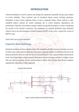
  • 2. INTRODUCTION Transient disturbances in power systems may damage key equipment, potentially having a great impact on system reliability. These transients may be introduced during normal switching operations, interruption of short circuits, lightning strikes, or due to equipment failure. Phasor analysis or other simplified analysis methods are usually inadequate due to system frequency dependencies and nonlinearities. Therefore, time-domain computer models are typically developed as a means of predicting the severity of the transient occurrences. The simulations are typically performed using simulation software such as the Electromagnetic Transient Program (EMTP). In this work, a royalty-free version of EMTP is used. Some of the cases are discussed below: Capacitor Bank Switching: During the switching of shunt capacitor banks, high magnitude and high frequency transients can occur. In earlier years, shunt capacitor banks have been more commonly installed at distribution and lower sub transmission levels. However, there has been a recent proliferation of new capacitor banks at transmission levels. Since larger higher-voltage capacitor banks have more stored energy and there is a higher system X/R ratio and less damping, this has raised concerns at utilities (like Northern States Power Company) regarding the vulnerability of their equipment. Figure: Capacitor Bank Switching Main Design
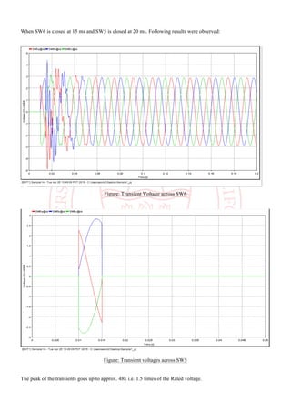
  • 3. When SW6 is closed at 15 ms and SW5 is closed at 20 ms. Following results were observed: Figure: Transient Voltage across SW6 Figure: Transient voltages across SW5 The peak of the transients goes up to approx. 48k i.e. 1.5 times of the Rated voltage.
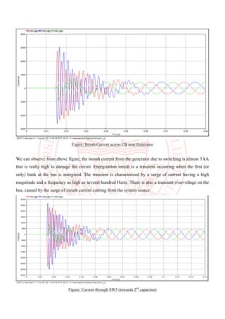
  • 4. Figure: Inrush Current across CB near Generator We can observe from above figure, the inrush current from the generator due to switching is almost 3 kA that is really high to damage the circuit. Energization inrush is a transient occurring when the first (or only) bank at the bus is energized. The transient is characterized by a surge of current having a high magnitude and a frequency as high as several hundred Hertz. There is also a transient overvoltage on the bus, caused by the surge of inrush current coming from the system source. Figure: Current through SW5 (towards 2nd capacitor)
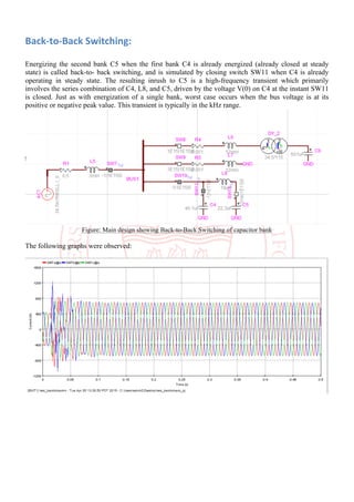
  • 5. Back-to-Back Switching: Energizing the second bank C5 when the first bank C4 is already energized (already closed at steady state) is called back-to- back switching, and is simulated by closing switch SW11 when C4 is already operating in steady state. The resulting inrush to C5 is a high-frequency transient which primarily involves the series combination of C4, L8, and C5, driven by the voltage V(0) on C4 at the instant SW11 is closed. Just as with energization of a single bank, worst case occurs when the bus voltage is at its positive or negative peak value. This transient is typically in the kHz range. Figure: Main design showing Back-to-Back Switching of capacitor bank The following graphs were observed:
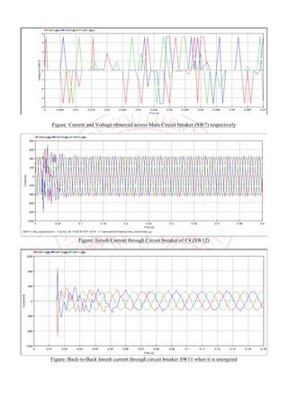
  • 6. Figure: Current and Voltage observed across Main Circuit breaker (SW7) respectively Figure: Inrush Current through Circuit breaker of C4 (SW12) Figure: Back-to-Back Inrush current through circuit breaker SW11 when it is energized
  • 7. Transformer Switching Transient: Transformer switching is the most commonly performed operation in any power delivery system and most of the times this operation can be performed without any undesirable consequences. However, given the right combination of system parameters, switching can result in a violent interaction between the circuit breaker and the transformer. This type of failures can best be explained by understanding as to how the switching induced transients are produced and how the transformer windings react to them. Switching transients can be produced by the breaker contact re-ignitions and / or by current chopping. Figure: Main Design for Transformer Switching (during High Inductive Load)
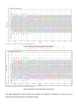
  • 8. Figure: High Inrush current through Circuit breaker 1 Figure: High Inrush current through Circuit breaker 2 This high magnitude of Inrush current may damage the windings of transformer. It may also cause blasting of the transformer due to Insulation damage.
  • 9. Figure : Voltage observed across Circuit breaker 1 Figure : Voltage observed across Circuit breaker 2 Controlled Switching can help to reduce the peaks (or eliminate) these high Inrush currents.
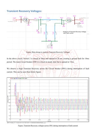
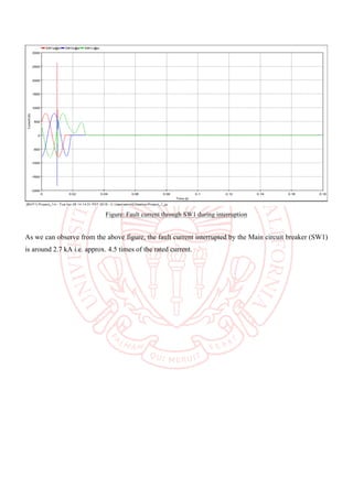
  • 10. Transient Recovery Voltages: Figure: Main design to analysis Transient Recovery Voltages In the above circuit, Switch 2 is closed at 10ms and opened at 20 ms, creating a ground fault for 10ms period. The main Circuit breaker (SW1) is closed at steady state but is opened at 15ms. We observe a High Transient Recovery across the Circuit breaker (SW1) during interruption of fault current. This can be seen from below figure: Figure: Transient Recovery voltages across SW1 during interruption of fault current
  • 11. Figure: Fault current through SW1 during interruption As we can observe from the above figure, the fault current interrupted by the Main circuit breaker (SW1) is around 2.7 kA i.e. approx. 4.5 times of the rated current.
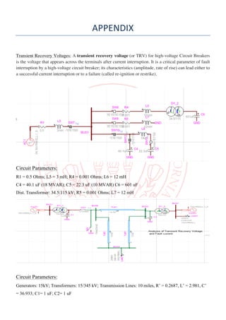
  • 12. APPENDIX Transient Recovery Voltages: A transient recovery voltage (or TRV) for high-voltage Circuit Breakers is the voltage that appears across the terminals after current interruption. It is a critical parameter of fault interruption by a high-voltage circuit breaker; its characteristics (amplitude, rate of rise) can lead either to a successful current interruption or to a failure (called re-ignition or restrike). Circuit Parameters: R1 = 0.5 Ohms; L5 = 3 mH; R4 = 0.001 Ohms; L6 = 12 mH C4 = 40.1 uF (18 MVAR); C5 = 22.3 uF (10 MVAR) C6 = 601 uF Dist. Transformer: 34.5/115 kV; R5 = 0.001 Ohms; L7 = 12 mH Circuit Parameters: Generators: 15kV; Transformers: 15/345 kV; Transmission Lines: 10 miles, R’ = 0.2687, L’ = 2.981, C’ = 36.933; C1= 1 uF; C2= 1 uF