Flip Flop and Its Types
2 likes2,838 views

Sequential Circuits, Flip-Flop Definition, Flip flop types, SR Flip Flop JK Flip Flop T Flip Flop D Flip Flop Uses of flip flop Each Type explanation, truth table and circuit diagram


More Related Content
What's hot (20)
More from Jancypriya M (10)


Recently uploaded (20)


Flip Flop and Its Types
- 1. Ms.M.Jancypriya, Assistant Professor, Department of BCA, Bon Secours College, Thanjavur, Tamilnadu, India FLIP-FLOP
- 2. Sequential Circuits • The output of circuit depends on the previous output and the present inputs. • The inputs must follow a specific sequence to produce a required output. • Most sequential systems are based on a small number of simple sequential circuit elements known as Bistables or Flip Flops. Ms.M.Jancypriya, Assistant Professor, Department of BCA, Bon Secours College, Thanjavur, Tamilnadu, India
- 3. Flip-Flop • In digital circuits, the flip-flop, is a kind of bistable multivibrator. • It is a Sequential Circuits / an electronic circuit which has two stable states and thereby is capable of serving as one bit of memory , bit 1 or bit 0. Ms.M.Jancypriya, Assistant Professor, Department of BCA, Bon Secours College, Thanjavur, Tamilnadu, India
- 4. FLIP-FLOP • Flip-flop have two stable conditions and can be switched from one to the other by appropriate inputs. These stable conditions are usually called the states of the circuit. • They are 1 (HIGH) or 0 (LOW) Whenever we refer to the state of flip flop, we refer to the state of its normal output (Q). • More complicated Flip flop use a clock as the control input. These clocked flip-flops are used whenever the input and output signals must occur within a particular sequence. Ms.M.Jancypriya, Assistant Professor, Department of BCA, Bon Secours College, Thanjavur, Tamilnadu, India
- 5. Types of Flip-Flop  SR Flip Flop  JK Flip Flop  T Flip Flop  D Flip Flop Ms.M.Jancypriya, Assistant Professor, Department of BCA, Bon Secours College, Thanjavur, Tamilnadu, India
- 6. Uses of Flip-Flop • For Memory circuits • For Logic Control Devices • For Counter Devices • Register Devices Ms.M.Jancypriya, Assistant Professor, Department of BCA, Bon Secours College, Thanjavur, Tamilnadu, India
- 7. SR Flip-Flop • The most basic Flip Flop is called SR Flip Flop. • The basic RS flip flop is an asynchronous device. • In asynchronous device, the outputs is immediately changed anytime one or more of the inputs change just as in combinational logic circuits. • It does not operate in step with a clock or timing. • These basic Flip Flop circuit can be constructed using two NAND gates latch or two NOR gates latch. • SR Flip Flop Active Low = NAND gates • SR Flip Flop Active High = NOR gates Ms.M.Jancypriya, Assistant Professor, Department of BCA, Bon Secours College, Thanjavur, Tamilnadu, India
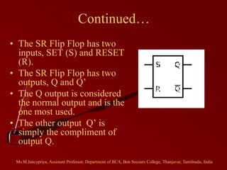
- 8. Continued… • The SR Flip Flop has two inputs, SET (S) and RESET (R). • The SR Flip Flop has two outputs, Q and Q’ • The Q output is considered the normal output and is the one most used. • The other output Q’ is simply the compliment of output Q. Ms.M.Jancypriya, Assistant Professor, Department of BCA, Bon Secours College, Thanjavur, Tamilnadu, India
- 9. Truth Table Ms.M.Jancypriya, Assistant Professor, Department of BCA, Bon Secours College, Thanjavur, Tamilnadu, India
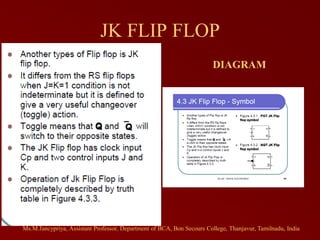
- 10. JK FLIP FLOP DIAGRAM Ms.M.Jancypriya, Assistant Professor, Department of BCA, Bon Secours College, Thanjavur, Tamilnadu, India
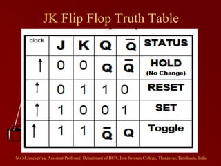
- 11. JK Flip Flop Truth Table Ms.M.Jancypriya, Assistant Professor, Department of BCA, Bon Secours College, Thanjavur, Tamilnadu, India
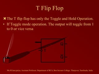
- 12. T Flip Flop The T flip flop has only the Toggle and Hold Operation. • If Toggle mode operation. The output will toggle from 1 to 0 or vice versa Ms.M.Jancypriya, Assistant Professor, Department of BCA, Bon Secours College, Thanjavur, Tamilnadu, India
- 13. Truth Table Ms.M.Jancypriya, Assistant Professor, Department of BCA, Bon Secours College, Thanjavur, Tamilnadu, India
- 14. D Flip Flop • Known as Data Flip flop • Can be constructed from RS Flip Flop or JK Flip flop by addition of an inverter. • Inverter is connected so that the R input is always the inverse of S (or J input is always complementary of K). • The D flip flop will act as a storage element for a single binary digit (Bit). Ms.M.Jancypriya, Assistant Professor, Department of BCA, Bon Secours College, Thanjavur, Tamilnadu, India
- 15. Truth Table and Diagram Ms.M.Jancypriya, Assistant Professor, Department of BCA, Bon Secours College, Thanjavur, Tamilnadu, India
- 16. Thank you…. Ms.M.Jancypriya, Assistant Professor, Department of BCA, Bon Secours College, Thanjavur, Tamilnadu, India