- Engineering curves include conic sections such as ellipses, parabolas, and hyperbolas which are obtained by cutting a right circular cone in different ways.
- An ellipse is obtained when the cutting plane is inclined to the axis and cuts all generators, producing a closed curve. A parabola results when the cutting plane is parallel to one generator. A hyperbola occurs when the cutting plane is inclined to one side of the axis.
- Conic sections can be defined using a focus and directrix, with eccentricity determining whether the curve is elliptical (e < 1), parabolic (e = 1), or hyperbolic (e > 1).
The document provides information on constructing conic sections like ellipses, parabolas, and hyperbolas using the eccentricity method. It gives step-by-step procedures to draw the curves based on the distance between the focus and directrix and the eccentricity. It also describes how to draw tangents and normals to these curves at any given point. Examples are included to practice constructing each type of conic section based on given parameters.
Lecture4 Engineering Curves and Theory of projections.pptxKishorKumaar3
Ìý
This document provides information about various types of plane curves generated by the motion of a circle or point rolling along another curve or line without slipping. It defines conic sections, which are curves formed by the intersection of a cone with a plane, including ellipses, parabolas, hyperbolas, and circles. It then discusses methods for constructing these conic sections geometrically using properties like eccentricity and foci. The document also covers roulettes like cycloids, epicycloids, hypocycloids, and trochoids formed by rolling motions, and provides examples of their geometric constructions.
Conics Sections and its Applications.pptxKishorKumaar3
Ìý
Conic sections are curves formed by the intersection of a cone with a plane. The type of conic section (triangle, circle, ellipse, parabola, hyperbola) depends on the position and orientation of the cutting plane relative to the cone's axis. Conic sections can be modeled and constructed using various methods that involve the focus, directrix, eccentricity, or arcs of circles. Roulettes are curves generated by the rolling contact of one curve on another without slipping, and include important types like cycloids, trochoids, and involutes that are used in engineering applications.
CURVE 1- THIS SLIDE CONTAINS WHOLE SYLLABUS OF ENGINEERING DRAWING/GRAPHICS. IT IS THE MOST SIMPLE AND INTERACTIVE WAY TO LEARN ENGINEERING DRAWING.SYLLABUS IS RELATED TO rajiv gandhi proudyogiki vishwavidyalaya / rajiv gandhi TECHNICAL UNIVERSITY ,BHOPAL.
This document provides information on engineering curves and conic sections. It describes different methods for drawing ellipses, parabolas, and hyperbolas including the concentric circle method, rectangle method, oblong method, and arcs of circle method. It also discusses drawing tangents and normals to these curves. Conic sections such as ellipses, parabolas, and hyperbolas are formed by cutting a cone with different plane sections. The ratio of a point's distances from a fixed point and fixed line is used to define eccentricity for these curves.
The document discusses various methods of drawing conic sections such as ellipses, parabolas, and hyperbolas. It provides details on the concentric circle method, rectangle method, oblong method, arcs of circle method, and general locus method for drawing ellipses. For parabolas, it describes the rectangle method, tangent method, and basic locus method. The hyperbola can be drawn using the rectangular hyperbola method, basic locus method, and through a given point with its coordinates. The document also discusses how to draw tangents and normals to these conic section curves from a given point.
The document provides information about engineering curves and their classification. It discusses that engineering curves are useful in nature, representing laws of nature on graphs. They are useful in engineering for understanding laws, manufacturing, design, analysis of forces, and construction. It then classifies key engineering curves like conics, cycloids, involutes, spirals, and helices. The document further explains different types of conics like circles, ellipses, parabolas, hyperbolas obtained from the intersection of a cutting plane with a right circular cone at different angles. It provides definitions and properties of each conic section. Finally, it discusses different methods to draw ellipses and parabolas like arc of circles, concentric circles, rectangle
The document discusses various types of engineering curves including conics, cycloids, involutes, spirals, and helices. It provides definitions and construction methods for different conic sections obtained from intersecting a right circular cone with cutting planes in different positions relative to the axis. Specifically, it describes how triangles, circles, ellipses, parabolas, and hyperbolas can be obtained and provides step-by-step methods for constructing ellipses using concentric circles, rectangles, oblongs, arcs of circles, and rhombuses. It also demonstrates how to construct parabolas and use directrix-focus definitions to draw ellipses, parabolas, and other curves.
EG Presentation (CONIC SECTIONS AND INVOLUTES) (1).pptxTulasi72
Ìý
This document defines and provides examples of constructing various conic sections (ellipse, parabola, hyperbola) and involutes (involute of a circle, triangle, hexagon). It begins by defining a conic section as the intersection of a plane and a circular cone, and describes the four types (circle, ellipse, parabola, hyperbola) based on the angle of the intersecting plane. Examples are given of constructing each conic section through marking points on extended lines. Real-world applications are also described for each conic section. Involutes are defined as loci traced by the end of a string wrapped around a curve. Constructions of involutes of a circle, triangle, and
This document provides methods for drawing three common conic sections - ellipses, parabolas, and hyperbolas. It outlines six methods for drawing ellipses, including the concentric circle method, rectangle method, and directrix-focus method. Two methods are described for drawing parabolas: the rectangle method and directrix-focus method. Three hyperbola problems are also shown, demonstrating the rectangular hyperbola, P-V diagram, and directrix-focus definition. Examples are given for each conic section with step-by-step instructions to draw the curves using the different techniques.
This document provides methods for drawing three common conic sections (ellipses, parabolas, and hyperbolas). It outlines six methods for drawing ellipses using concentric circles, rectangles, oblongs, arcs of circles, rhombi, and the directrix-focus definition. Two methods are given for drawing parabolas using rectangles and the directrix-focus definition. Hyperbolas can be drawn using rectangular hyperbolas based on coordinates or P-V diagrams, and the directrix-focus definition. The document also demonstrates how to draw tangents and normals to these curves from a given point using properties of their geometric definitions.
This document provides methods for drawing three conic sections (ellipse, parabola, and hyperbola) and calculating tangents and normals to these curves. It outlines six methods for drawing ellipses, including the concentric circle, rectangle, and directrix-focus definitions. Two methods are described for drawing parabolas and three examples of hyperbolas, including the P-V diagram representation. The final section demonstrates how to determine the tangent and normal lines to these conic sections from a given point using properties of directrix and focus.
The document describes various methods for drawing three common conic sections: ellipses, parabolas, and hyperbolas. It provides step-by-step instructions for constructing each conic section using different geometric techniques, such as the concentric circles method, rectangle method, and directrix-focus definition. Examples are given for each construction method along with diagrams illustrating the steps. Common properties of the three conic sections are also defined, such as their relationships to a cone and definitions involving eccentricity.
This document provides definitions and examples of common engineering curves including involutes, cycloids, spirals, and helices. It begins by listing different types of involutes defined by the string length relative to the circle's circumference. Definitions are then given for cycloids based on whether the rolling circle is inside or outside the directing circle. Superior and inferior trochoids are distinguished based on this as well. Spirals are defined as curves generated by a point revolving around a fixed point while also moving toward it. Helices are curves generated by a point moving around a cylinder or cone surface while advancing axially. Examples are provided for drawing various curves along with methods for constructing tangents and normals.
Curves2- THIS SLIDE CONTAINS WHOLE SYLLABUS OF ENGINEERING DRAWING/GRAPHICS. IT IS THE MOST SIMPLE AND INTERACTIVE WAY TO LEARN ENGINEERING DRAWING.SYLLABUS IS RELATED TO rajiv gandhi proudyogiki vishwavidyalaya / rajiv gandhi TECHNICAL UNIVERSITY ,BHOPAL.
The document discusses various engineering curves including conic sections like ellipses, parabolas and hyperbolas. It provides definitions and methods of constructing these curves. Specifically, it outlines six methods of constructing ellipses including the concentric circle, rectangle, oblong, arcs of circle, rhombus and directrix-focus methods. It also describes three methods of constructing parabolas and hyperbolas including the rectangle method, method of tangents and directrix-focus method. Additionally, it discusses drawing tangents and normals to these curves.
This document provides methods for drawing three common conic sections (curves): ellipses, parabolas, and hyperbolas. It outlines six different methods for constructing ellipses, including the concentric circle, rectangle, oblong, arcs of circles, rhombus, and directrix-focus methods. Two methods are described for drawing parabolas: the rectangle method and method of tangents. And three examples are given for hyperbolas: the rectangular hyperbola using coordinates, the P-V diagram, and the directrix-focus method. The document also explains how to draw tangents and normals to these curves from a given point.
The document provides information about various plane curves covered in the Engineering Graphics course GE8152 Unit 1. It includes definitions and methods for constructing conic sections like circles, ellipses, parabolas and hyperbolas on a plane. It also describes construction of other curves like cycloids, epicycloids, hypocycloids, involutes of circles and squares. Detailed step-by-step processes are provided with diagrams to draw these curves using basic geometrical concepts like loci, tangents, normals and eccentricity.
The document provides information about various plane curves covered in the Engineering Graphics course GE8152 Unit 1. It includes definitions and methods for constructing conic sections like circles, ellipses, parabolas and hyperbolas on a plane. It also describes the construction of other curves like cycloids, epicycloids, hypocycloids, involutes of circles and squares. Detailed step-by-step processes are provided with diagrams to draw these curves using focus, directrix, radii and other geometric properties. The document serves as a reference for students to understand and construct different plane curves for applications in engineering graphics.
The document describes various engineering curves including conic sections like ellipses, parabolas, and hyperbolas. It provides different methods for constructing these curves, such as the concentric circle method, rectangle method, and directrix-focus method. It also discusses drawing tangents and normals to the curves. Other curves covered include involutes, cycloids, trochoids, spirals, and helices. The document contains examples demonstrating how to apply these construction techniques to draw the curves based on given parameters.
This document provides information on various types of engineering curves including conic curves, spirals, cycloids and involutes. It discusses the different methods for drawing ellipses including the concentric circle, rectangular, oblong, arc of circle and rhombus methods. The document also covers drawing parabolas using the rectangle, tangent and directrix-focus methods. Additionally, it demonstrates how to draw a hyperbola through a given point and construct tangents and normals to ellipses and hyperbolas at a specified point.
The document discusses different types of engineering curves known as conics that are formed by the intersection of a cutting plane with a cone. These conics include ellipses, parabolas, hyperbolas, circles, and triangles. The document provides definitions, examples of uses, and methods for drawing each type of conic section. It specifically describes how to construct ellipses, parabolas, and hyperbolas using different geometric techniques such as the arc of a circle, concentric circles, directrix-focus, and rectangular methods.
The document provides information on geometric constructions of conic sections. It defines conic sections as curves formed by the intersection of a plane and a cone, including circles, ellipses, parabolas, and hyperbolas. It then describes several methods for constructing each type of conic section geometrically, such as using concentric circles to draw an ellipse, the focus-directrix definition to draw parabolas, and locus properties involving distances from two focal points to draw hyperbolas. Diagrams illustrate each construction method.
This document provides information on engineering curves and their uses. It discusses various types of curves including conics, cycloidal curves, involutes, spirals, helices, sine and cosine curves. It describes what a cone is and the different types of cones. It then explains the five basic conic sections - triangle, circle, ellipse, parabola, and hyperbola that are obtained by cutting a right circular cone with different cutting planes. Various properties and uses of ellipses, parabolas, and hyperbolas are also covered. Finally, it discusses different methods for drawing these curves.
Vector integrals generalize integration to vector-valued functions. Line integrals measure the accumulated effect of a vector field along a curve, surface integrals measure flux through a surface, and volume integrals measure the total effect within a region. Vector integrals are used widely in physics and engineering to calculate quantities such as work, magnetic flux, and fluid flow.
Formal letters have a specific structure and format. They are used for professional communication regarding work concerns, orders, applications and addressing problems. A formal letter includes the sender's address, date, recipient's address, salutation, subject, body organized in paragraphs, complimentary close and signature. The body should be brief, clear, precise and polite. Common complimentary closes are "Yours sincerely" or "Yours faithfully". Formal letters follow a block, modified block or semi-block format to organize the elements in a clear, readable way.
Linear probing is a technique for resolving collisions in hash tables that uses open addressing. When a collision occurs inserting a key-value pair, linear probing searches through the hash table sequentially from the hashed index to find the next empty slot to insert the pair. This provides high performance due to locality of reference. The linear probing hash table stores data directly in the array, handling collisions by probing through subsequent indices in the table until an empty slot is found to insert the new pair. Insertion, search, and deletion operations take constant expected time on average when using a random hash function.
This document discusses solving systems of linear equations using matrix methods. It begins by defining a matrix and explaining how to write the augmented matrix of a system of linear equations. It then describes three row operations that can be performed on matrices: exchanging rows, multiplying a row by a non-zero number, and adding a multiple of one row to another. Examples are provided of using these row operations to solve systems with two and three variables and put the augmented matrix in row echelon form. The document concludes by discussing how to recognize inconsistent or dependent systems.
Doubly linked lists are lists where each node contains a pointer to the next node and previous node. Each node stores data and pointers to the next and previous nodes. Finding a node requires searching the list using the next pointers until the desired node is found or the end is reached. Inserting a node involves finding the correct location and adjusting the next and previous pointers of the neighboring nodes. Headers and trailers can simplify insertion and deletion by avoiding special cases for the first and last nodes. Large integers can be represented using a special linked list implementation that treats each digit as a node.
1. The document discusses three external water softening processes: lime-soda process, zeolite process, and ion exchange process.
2. The lime-soda process uses lime and soda ash to precipitate calcium and magnesium ions from water. The zeolite process uses naturally occurring minerals to exchange sodium ions for calcium and magnesium ions. The ion exchange process uses cation and anion exchange resins to remove ions from water.
3. Each process has advantages like reducing hardness and corrosion but also limitations such as producing waste sludge or requiring pre-treatment of the raw water.
This document describes a chemistry lab experiment to determine the concentration of HCl using conductometric titration with NaOH. The key steps are:
1) 40ml of HCl is titrated with 0.1M NaOH solution while measuring the conductance.
2) The conductance is plotted against the volume of NaOH added.
3) The neutralization point is determined from the graph by extrapolating the straight lines.
4) Using the titration data and volume of HCl, the molarity of HCl is calculated to be 0.015M.
This document provides an introduction and overview of biodiesel. It discusses what biodiesel is, how it is made from vegetable and animal fats, its fuel properties, issues related to vehicle operation and engine impacts, current fuel costs, distribution challenges, existing policies and programs supporting biodiesel, and areas for future attention and research. The purpose is to inform a technical subcommittee about biodiesel and address increasing interest in its use.
1. Fuels are combustible substances containing mainly carbon that produce heat energy when burned. Coal, petroleum, and natural gas are important primary fossil fuels found naturally.
2. Fuels can be classified based on their physical state as solid, liquid, or gaseous. They can also be classified as primary fuels found in nature or secondary fuels derived from primary fuels.
3. The calorific value of a fuel is the amount of heat released during complete combustion. It is usually measured in kilocalories per kilogram. Higher calorific value includes the heat of condensation of water vapor produced, while lower calorific value does not.
This document provides definitions and examples of different types of matrices including: real matrix, square matrix, row matrix, column matrix, null matrix, sub-matrix, diagonal matrix, scalar matrix, unit matrix, upper triangular matrix, lower triangular matrix, triangular matrix, single element matrix, equal matrices, singular and non-singular matrices. It also discusses elementary row and column transformations, rank of a matrix, solutions to homogeneous and non-homogeneous systems of linear equations, characteristic equations, eigenvectors and eigenvalues.
This document summarizes Kirchoff's laws, which are two circuit analysis laws developed by Gustav Kirchoff. Kirchoff's Current Law (KCL) states that the algebraic sum of currents entering a node is zero. Kirchoff's Voltage Law (KVL) states that the algebraic sum of the voltages around any closed loop in a circuit must be zero. The document provides examples of applying KCL and KVL to solve for currents in circuits containing meshes and nodes. It determines the current through an 8 ohm resistor by setting up KCL and KVL equations and solving the system of equations.
Optimization of Cumulative Energy, Exergy Consumption and Environmental Life ...J. Agricultural Machinery
Ìý
Optimal use of resources, including energy, is one of the most important principles in modern and sustainable agricultural systems. Exergy analysis and life cycle assessment were used to study the efficient use of inputs, energy consumption reduction, and various environmental effects in the corn production system in Lorestan province, Iran. The required data were collected from farmers in Lorestan province using random sampling. The Cobb-Douglas equation and data envelopment analysis were utilized for modeling and optimizing cumulative energy and exergy consumption (CEnC and CExC) and devising strategies to mitigate the environmental impacts of corn production. The Cobb-Douglas equation results revealed that electricity, diesel fuel, and N-fertilizer were the major contributors to CExC in the corn production system. According to the Data Envelopment Analysis (DEA) results, the average efficiency of all farms in terms of CExC was 94.7% in the CCR model and 97.8% in the BCC model. Furthermore, the results indicated that there was excessive consumption of inputs, particularly potassium and phosphate fertilizers. By adopting more suitable methods based on DEA of efficient farmers, it was possible to save 6.47, 10.42, 7.40, 13.32, 31.29, 3.25, and 6.78% in the exergy consumption of diesel fuel, electricity, machinery, chemical fertilizers, biocides, seeds, and irrigation, respectively.
Lecture -3 Cold water supply system.pptxrabiaatif2
Ìý
The presentation on Cold Water Supply explored the fundamental principles of water distribution in buildings. It covered sources of cold water, including municipal supply, wells, and rainwater harvesting. Key components such as storage tanks, pipes, valves, and pumps were discussed for efficient water delivery. Various distribution systems, including direct and indirect supply methods, were analyzed for residential and commercial applications. The presentation emphasized water quality, pressure regulation, and contamination prevention. Common issues like pipe corrosion, leaks, and pressure drops were addressed along with maintenance strategies. Diagrams and case studies illustrated system layouts and best practices for optimal performance.
How to Build a Maze Solving Robot Using ArduinoCircuitDigest
Ìý
Learn how to make an Arduino-powered robot that can navigate mazes on its own using IR sensors and "Hand on the wall" algorithm.
This step-by-step guide will show you how to build your own maze-solving robot using Arduino UNO, three IR sensors, and basic components that you can easily find in your local electronics shop.
This presentation provides an in-depth analysis of structural quality control in the KRP 401600 section of the Copper Processing Plant-3 (MOF-3) in Uzbekistan. As a Structural QA/QC Inspector, I have identified critical welding defects, alignment issues, bolting problems, and joint fit-up concerns.
Key topics covered:
✔ Common Structural Defects – Welding porosity, misalignment, bolting errors, and more.
✔ Root Cause Analysis – Understanding why these defects occur.
✔ Corrective & Preventive Actions – Effective solutions to improve quality.
✔ Team Responsibilities – Roles of supervisors, welders, fitters, and QC inspectors.
✔ Inspection & Quality Control Enhancements – Advanced techniques for defect detection.
📌 Applicable Standards: GOST, KMK, SNK – Ensuring compliance with international quality benchmarks.
🚀 This presentation is a must-watch for:
✅ QA/QC Inspectors, Structural Engineers, Welding Inspectors, and Project Managers in the construction & oil & gas industries.
✅ Professionals looking to improve quality control processes in large-scale industrial projects.
📢 Download & share your thoughts! Let's discuss best practices for enhancing structural integrity in industrial projects.
Categories:
Engineering
Construction
Quality Control
Welding Inspection
Project Management
Tags:
#QAQC #StructuralInspection #WeldingDefects #BoltingIssues #ConstructionQuality #Engineering #GOSTStandards #WeldingInspection #QualityControl #ProjectManagement #MOF3 #CopperProcessing #StructuralEngineering #NDT #OilAndGas
Preface: The ReGenX Generator innovation operates with a US Patented Frequency Dependent Load
Current Delay which delays the creation and storage of created Electromagnetic Field Energy around
the exterior of the generator coil. The result is the created and Time Delayed Electromagnetic Field
Energy performs any magnitude of Positive Electro-Mechanical Work at infinite efficiency on the
generator's Rotating Magnetic Field, increasing its Kinetic Energy and increasing the Kinetic Energy of
an EV or ICE Vehicle to any magnitude without requiring any Externally Supplied Input Energy. In
Electricity Generation applications the ReGenX Generator innovation now allows all electricity to be
generated at infinite efficiency requiring zero Input Energy, zero Input Energy Cost, while producing
zero Greenhouse Gas Emissions, zero Air Pollution and zero Nuclear Waste during the Electricity
Generation Phase. In Electric Motor operation the ReGen-X Quantum Motor now allows any
magnitude of Work to be performed with zero Electric Input Energy.
Demonstration Protocol: The demonstration protocol involves three prototypes;
1. Protytpe #1, demonstrates the ReGenX Generator's Load Current Time Delay when compared
to the instantaneous Load Current Sine Wave for a Conventional Generator Coil.
2. In the Conventional Faraday Generator operation the created Electromagnetic Field Energy
performs Negative Work at infinite efficiency and it reduces the Kinetic Energy of the system.
3. The Magnitude of the Negative Work / System Kinetic Energy Reduction (in Joules) is equal to
the Magnitude of the created Electromagnetic Field Energy (also in Joules).
4. When the Conventional Faraday Generator is placed On-Load, Negative Work is performed and
the speed of the system decreases according to Lenz's Law of Induction.
5. In order to maintain the System Speed and the Electric Power magnitude to the Loads,
additional Input Power must be supplied to the Prime Mover and additional Mechanical Input
Power must be supplied to the Generator's Drive Shaft.
6. For example, if 100 Watts of Electric Power is delivered to the Load by the Faraday Generator,
an additional >100 Watts of Mechanical Input Power must be supplied to the Generator's Drive
Shaft by the Prime Mover.
7. If 1 MW of Electric Power is delivered to the Load by the Faraday Generator, an additional >1
MW Watts of Mechanical Input Power must be supplied to the Generator's Drive Shaft by the
Prime Mover.
8. Generally speaking the ratio is 2 Watts of Mechanical Input Power to every 1 Watt of Electric
Output Power generated.
9. The increase in Drive Shaft Mechanical Input Power is provided by the Prime Mover and the
Input Energy Source which powers the Prime Mover.
10. In the Heins ReGenX Generator operation the created and Time Delayed Electromagnetic Field
Energy performs Positive Work at infinite efficiency and it increases the Kinetic Energy of the
system.
15. Smart Cities Big Data, Civic Hackers, and the Quest for a New Utopia.pdfNgocThang9
Ìý
Lecture 2 Engineering curves.pdf
1. 8/1/2014
1
Lecture 2: Engineering Curves
1
Engineering Curves
• used in designing certain objects
Conic Sections
• Sections of a right circular cone obtained by
cutting the cone in different ways
• Depending on the position of the cutting plane
relative to the axis of cone, three conic sections
can be obtained
– ellipse,
– parabola and
– hyperbola
2
2. 8/1/2014
2
Conic Sections
• An ellipse is obtained when a section
plane A–A, inclined to the axis cuts all
the generators of the cone.
• A parabola is obtained when a section
plane B–B, parallel to one of the
generators cuts the cone. Obviously, the
section plane will cut the base of the
cone.
• A hyperbola is obtained when a section
plane C–C, inclined to the axis cuts the
cone on one side of the axis.
• A rectangular hyperbola is obtained
when a section plane D–D, parallel to
the axis cuts the cone.
A
A
B
B
C
C
D
D
O
O
3
4
3. 8/1/2014
3
Conic is defined as locus of a point moving in a plane such that the
ratio of its distance from a fixed point (F) to the fixed straight line is
always a constant. This ratio is called as eccentricity.
Ellipse: eccentricity is always <1
Parabola: eccentricity is always=1
Hyperbola: eccentricity is >1
The fixed point is called the Focus
The fixed line is called the Directrix
Axis is the line passing though the
focus and perpendicular to the
directrix
Vertex is a point at which the conic
cuts its axis VC
VF
e =
5
• Eccentricity is less than 1.
• Closed curve.
• The fixed points represent the foci.
• The sum of the distances of a point on the
ellipse from the two foci is equal to the major
axis
• The distance of any end of the minor axis
from any focus is equal to the half of the
major axis
Relationship between Major axis, Minor axis and Foci
• If major axis and minor axis are given, the
two fixed points F1 and F2 can be located
with the following fact
• If minor axis is given instead of the distance between the foci, then locate the foci F and
F’ by cutting the arcs on major axis with C as a center and radius= ½ major axis= OA
Ellipse
6
4. 8/1/2014
4
An ellipse has two foci (F and F’), two directrices (AB and A’B’ ), two
axes (V–V’ and V 1–V 1’) and four vertices (V, V’, V 1 and V 1’ ). The
two axes are called the major axis and minor axis.
7
Methods for Generating Ellipse
1. Focus-Directrix Or Eccentricity Method
– General method of constructing any conics when the
distance of the focus from the directrix and its
eccentricity are given.
2. Concentric Method
– This method is applicable when the major axis and
minor axis of an ellipse are given.
3. Oblong Method
– This method is applicable when the major axis and
minor axis or the conjugate axes with the angle
between them is given.
8
5. 8/1/2014
5
Types of Problems
• Focus-Directrix Or Eccentricity Method
– Draw an ellipse if the distance of the focus from the
directrix 50 mm and the eccentricity is 2/3
– Draw a parabola if the distance of the focus from the
directrix is 55 mm
– Draw a hyperbola of e = 4/3 if the distance of the focus
from the directrix = 60 mm
• Concentric Method
– Draw an ellipse having the major axis of 60 mm and the
minor axis of 40 mm
• Oblong Method
– Draw an ellipse having conjugate axes of 60 mm and 40
mm long and inclined at 750 to each other
9
F1
V1
D
D
1 2 3 4 5
11
21
31
41
51
C
V2
Focus-Directrix or Eccentricity Method
10
45
Slope of line is e
6. 8/1/2014
6
Focus-Directrix or Eccentricity Method
11
Q.1: Draw an ellipse if the distance of focus from the directrix is 70 mm and the
eccentricity is 3/4.
1. Draw the directrix and axis as shown.
2. Mark F on axis such that CF 1= 70 mm.
3. Divide CF into 3 + 4 = 7 equal parts and mark V at the fourth division from C.
Now, e = FV/ CV = 3/4.
4. At V, erect a perpendicular VB = VF. Join CB.
5. Through F, draw a line at 45° to meet CB produced at D. Through D, drop a
perpendicular DV’ on CC’. Mark O at the midpoint of V– V’.
6. Mark a few points, 1, 2, 3, … on V– V’ and erect perpendiculars though them
meeting CD at 1’, 2’, 3’…. Also erect a perpendicular through O.
7. With F as a centre and radius = 1–1’, cut two arcs on the perpendicular through 1
to locate P1 and P1¢. Similarly, with F as a centre and radii = 2–2’, 3–3’, etc., cut
arcs on the corresponding perpendiculars to locate P/2 and P/2’, P/3 and P/3’,
etc. Also, cut similar arcs on the perpendicular through O to locate V1 and V1’.
Steps for Focus-Directrix or Eccentricity Method
12
7. 8/1/2014
7
A B
C
D
O
1’ 2’ 3’
1
3
2
P1
P2
P3
Oblong Method
13
Steps for Oblong Method
Draw an ellipse with a 70 mm
long major axis and a 45 mm
long minor axis.
or
Draw an ellipse circumscribing
a rectangle having sides 70 mm
and 45 mm.
1. Draw the major axis AB = 70 mm and minor axis CD = 45 mm, bisecting each other
at right angles at O.
2. Draw a rectangle EFGH such that EF = AB and FG = CD.
3. Divide AO and AE into same number of equal parts, say 4. Number the divisions as
1, 2, 3 and 1’, 2’, 3’, starting from A.
4. Join C with 1, 2 and 3.
5. Join D with 1’ and extend it to meet C–1 at P1. Similarly, join D with 2’ and 3’ and
extend them to meet C–2 and C–3 respectively to locate P/2 and P/3. 14
8. 8/1/2014
8
Concentric Circle Method
15
A B
C
D
Draw an ellipse having the major
axis of 70 mm and the minor axis
of 40 mm.
Draw the major axis AB = 70 mm
and minor axis CD = 40 mm,
bisecting each other at right angles
at O.
Draw two circles with AB and CD
as diameters. Divide both the
circles into 12 equal parts and
number the divisions as A, 1, 2, 3, …
10, B and C, 1’, 2’, 3’ … 10’, D.
Through 1, draw a line parallel to CD. Through 1’, draw a line parallel to AB. Mark P1 at
their intersection.
Obtain P/2, P4, P5, etc., in a similar way.
Draw a smooth closed curve through A– P1–P/2– C– P4– P5– B– P6– P7– D– P/9– P10–
A.
Concentric Circle Method
16
9. 8/1/2014
9
Tangent and Normal at any point P
17
Draw ellipse using Focus-Directrix or Eccentricity Method
F
P
Q
Tangent
Normal
1. Mark the given point P and join
PF1 .
2. At F1 draw a line perpendicular to
PF1 to cut DD at Q.
3. Join QP and extend it. QP is the
tangent at P
4. Through P, draw a line NM
perpendicular to QP. NM is the
normal at P
18
10. 8/1/2014
10
Tangent and Normal at any point P when Focus and Directrix are
not known
1. First obtain the foci F and
F′ by cutting the arcs on
major axis with C as a
centre and radius =OA
2. Obtain NN, the bisector of
∠FPF′. N-N is the
required normal
3. Draw TT perpendicular to
N-N at P. T-T is the
required tangent
19
Few Applications of Ellipse
Elliptical gear
Arch
Bullet nose
20
11. 8/1/2014
11
Parabola
• A parabola is a conic whose eccentricity is equal to 1. It is an open-
end curve with a focus, a directrix and an axis.
• Any chord perpendicular to the axis is called a double ordinate.
• The double ordinate passing through the focus . i.e LL’ represents the
latus rectum
• The shortest distance of the vertex from any ordinate, is known as the
abscissa.
21
Methods for Generating Parabola
1. Focus-Directrix Or Eccentricity Method
– General method of constructing any conics when the distance of the
focus from the directrix
– For example, draw a parabola if the distance of the focus from the
directrix is 55 mm.
2. Rectangle Method and Parallelogram Method
– This method is applicable when the axis (or abscissa) and the base ( or
double ordinate) of a parabola are given or the conjugte axes with the
angle between them is given
– For example, draw a parabola having an abscissa of 30 mm and the
double ordinate are 70 mm, or
– Draw an parabola having conjugate axes of 60 mm and 40 mm long
and inclined at 750 to each other.
3. Tangent Method
– This method is applicable when the base and the inclination of
tangents at open ends of the parabola with the base are given
– For example, draw a parabola if the base is 70 mm and the tangents at
the base ends make 60° to the base..
22
12. 8/1/2014
12
Focus-Directrix Or Eccentricity Method
• Distance of the focus from the directrix is known.
23
F
C C’
A
B
V
CV = VF
E EV = VF
D
Slope of CD is e = 1
1 2 3 4
1’
2’
3’
4’
Center = F
Radius = 1-1’
`
`
`
`
1. Draw directrix AB and axis CC’ as shown.
2. Mark F on CC’ such that CF = 60 mm.
3. Mark V at the midpoint of CF. Therefore, e = VF/
VC = 1.
4. At V, erect a perpendicular VB = VF. Join CB.
5. Mark a few points, say, 1, 2, 3, … on VC’ and erect
perpendiculars through them meeting CB
produced at 1’, 2’, 3’, …
6. With F as a centre and radius = 1–1’, cut two arcs
on the perpendicular through 1 to locate P1 and
P1’. Similarly, with F as a centre and radii = 2–2’,
3–3’, etc., cut arcs on the corresponding
perpendiculars to locate P2 and P2’, P3 and P3’,
etc.
7. Draw a smooth curve passing through V, P1, P2,
P3 … P3
Draw a parabola if the distance of the focus from the directrix is 60 mm.
Steps for Focus-Directrix or Eccentricity Method
24
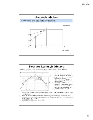
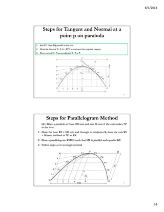
13. 8/1/2014
13
Rectangle Method
• Abscissa and ordinate are known.
25
A B
AB-Ordinate
C
D
CD-Abscissa
1 2
1’
2’
1. Draw the double ordinate RS = 70
mm. At midpoint K erect a
perpendicular KV = 30 mm to
represent the abscissa.
2. Construct a rectangle RSMN such
that SM = KV.
3. Divide RN and RK into the same
number of equal parts, say 5.
Number the divisions as 1, 2, 3, 4
and 1’, 2’, 3’, 4’, starting from R.
4. Join V–1, V–2, V–3 and V–4.
Q.1: Draw a parabola having an abscissa of 30 mm and the double ordinate of 70 mm.
5. Through 1’, 2’, 3’ and 4’, draw lines parallel to KV to meet V–1 at P1, V–2 at P2, V–3 at P3 and V–4 at
P4, respectively.
6. Obtain P5, P6, P7 and P8 in the other half of the rectangle in a similar way. Alternatively, these
points can be obtained by drawing lines parallel to RS through P1, P2, P3 and P4. For example, draw
P1– P8 such that P1– x = x– P8.
7. Join P1, P2, P3 … P8 to obtain the parabola.
Steps for Rectangle Method
26
14. 8/1/2014
14
Steps for Tangent and Normal at a
point p on parabola
1. Join PF. Draw PQ parallel to the axis.
2. Draw the bisector T– T of – FPQ to represent the required tangent.
3. Draw normal N– N perpendicular T– T at P.
27
Steps for Parallelogram Method
Q.1: Draw a parabola of base 100 mm and axis 50 mm if the axis makes 70°
to the base.
1. Draw the base RS = 100 mm and through its midpoint K, draw the axis KV
= 50 mm, inclined at 70° to RS.
2. Draw a parallelogram RSMN such that SM is parallel and equal to KV.
3. Follow steps as in rectangle method
28
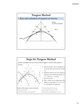
15. 8/1/2014
15
Tangent Method
• Base and inclination of tangents are known.
29
R S
L
RS-Base
RL and SL are tangents
1
2
3 1’
2’
3’
P
S
V
VR=VS
R
Tangent
Method to draw tangent at a point on parabola 1. First locate the point P on the curve
2. Draw the ordinate PS 3. On LK, mark T such that TV =VS
4. Join TP and extend to obtain tangent TT 5.Draw normal N-N perpendicular to T-T at P
1. Draw the base RS = 70 mm. Through R and
S, draw the lines at 60° to the base, meeting
at L.
2. Divide RL and SL into the same number of
equal parts, say 6. Number the divisions as 1,
2, 3 … and 1’, 2’, 3’, … as shown.
3. Join 1–1’, 2–2’, 3–3’, ….
4. Draw a smooth curve, starting from R and
ending at S and tangent to 1–1’, 2–2’, 3–3’,
etc., at P1, P2, P3, etc., respectively
Q. Draw a parabola if the base is 70 mm and the tangents at the base ends make 60° to
the base.
Steps for Tangent Method
30
16. 8/1/2014
16
To find the focus and the directrix of a parabola given its axis
Tangent and Normal at any point P when Focus and
Directrix are not known
1. Draw the ordinate PQ
2. Find the abscissa VQ
3. Mark R on CA such that RV=VQ
4. Draw the normal NM perpendicular to RP at P
1. Mark any point P on the parabola
2. Draw a perpendicular PQ to the given axis
3. Mark a point R on the axis such that RV=VQ
4. Focus: Join RP. Draw a perpendicular bisector of RP
cutting the axis at F, F is the focus
5. Directrix: Mark O on the axis such that OV= VF. Through
O draw the directrix DD perpendicular to the axis 31
Few Applications of Parabola
32