Lecture 8 Decoders & Encoders (combinational circuits)
0 likes31 views
The document explains the concepts of decoders and encoders in digital circuits. A decoder is a combinational logic circuit that activates a single output corresponding to a binary input number, whereas an encoder converts data from one form to another. The document also discusses applications, truth tables, implementations, and addresses potential issues with encoders, including ambiguity when multiple inputs are active.
1 of 29
Download to read offline
Ad
Recommended
DECODER AND ENCODER (1).pptx
DECODER AND ENCODER (1).pptxFATHIMATHASLIMAMScCo
╠²
The document discusses different types of decoders and encoders used in digital electronics. It describes 2-to-4 line, 3-to-8 line, and 4-to-16 line decoders that convert binary input to decoded output lines. Encoder types covered include 4-to-2 line, 8-to-3 line, and decimal-to-BCD encoders that convert encoded input lines to binary output. Truth tables and logic diagrams are provided for each circuit. Priority encoders that prioritize inputs are also summarized.Encoder.pptx
Encoder.pptxPooja Dixit
╠²
This document discusses encoders and provides examples of 4-to-2 and 8-to-3 line encoders. It defines an encoder as a combinational circuit that performs the reverse operation of a decoder, with a maximum of 2n input lines and n output lines. Truth tables and logic circuits are given for 4-to-2 and 8-to-3 line encoders. Uses of encoders include converting decimal to binary numbers to perform binary operations like addition and subtraction in digital systems.Decoders
DecodersPooja Dixit
╠²
A decoder is a logic circuit that takes binary input and provides an output based on the input. It performs the reverse operation of an encoder. There are different types of decoders including a 2 to 4 line decoder and a 3 to 8 line decoder. A 2 to 4 line decoder has 3 inputs (A0, A1, E) and 4 outputs (Y0, Y1, Y2, Y3). It uses AND gates to activate one output based on the input. A 3 to 8 line decoder has 3 inputs (A0, A1, A2), 8 outputs (Y0-Y7), and an enable input. It uses AND gates and logic expressions to activate one of the 8 outputs based on theSESSION 2.ppt
SESSION 2.pptSaranya S
╠²
The document presents an educational presentation on digital logic circuits, particularly focusing on decoders, encoders, multiplexers, and demultiplexers. It explains how these components operate, including their truth tables, logic diagrams, and applications in digital systems. Key topics include the functionality of binary and BCD-to-7 segment decoders, octal-to-binary encoders, and the construction of multiplexers and demultiplexers.Encoders anaaaaaaaaaaaaaaad decoders.pdf
Encoders anaaaaaaaaaaaaaaad decoders.pdfAdityaGupta221734
╠²
The document describes decoders and encoders as combinational circuits used for encoding and decoding binary numbers. A decoder activates one output corresponding to the input binary number, while an encoder converts an active input to a coded output signal. It includes details about different types of decoders and encoders, their block diagrams, input-output relationships, and the truth tables associated with them.digital-electronics_9 encoder and decoder pdf
digital-electronics_9 encoder and decoder pdfsomanathbtech
╠²
An encoder is a combinational logic circuit that converts active inputs, representing digits or symbols, into coded outputs like binary or BCD. Priority encoders not only encode input signals but also determine precedence among multiple active inputs, with a valid bit indicating whether any input is active. Key applications include digital encoders for keyboards and various encode-decode operations in electronic systems.Decodder presentation by ibrar
Decodder presentation by ibraribrar562
╠²
1) A decoder is a circuit that converts binary input into octal or decimal output by activating one of its output lines. It has fewer output lines than input lines.
2) An encoder performs the reverse operation of a decoder - it converts octal or decimal input into binary output. It has fewer input lines than output lines.
3) A multiplexer is a circuit that selects one of several input lines and directs it to a single output line based on the value of a selection input. It allows transmission of multiple information over fewer channels.Encoders
EncodersDaffodil International University
╠²
This document discusses encoders. It defines an encoder as a device, circuit, transducer, software program, algorithm, or person that converts information from one format to another. It provides examples of different types of encoders, including:
- Binary encoders, which have 2n inputs and n outputs, with one of the 2n inputs set to 1 and the output being an n-bit binary number.
- Linear encoders, which are sensors with a scale that encodes position and converts the encoded position into an analog or digital signal.
- Digital encoders, also called binary encoders, that take data inputs one at a time and convert them into a single encoded output. Common configurations include 4Decoders decoderand design with their.pptx
Decoders decoderand design with their.pptxssuser67a684
╠²
The document explains the concepts of decoding and encoding in digital circuits, detailing how decoders convert n-bit input codes to unique output codes and encoders perform the opposite function. It includes block diagrams, truth tables, and output equations for both a 2-to-4 decoder and an 8-to-3 encoder. These components are fundamental in digital electronics for managing binary code representation.B sc3 unit 4 combi..lckt
B sc3 unit 4 combi..lcktMahiboobAliMulla
╠²
1. The document discusses combinational logic circuits and describes various types including half adders, full adders, decoders, encoders, multiplexers, and comparators.
2. It provides truth tables and logic expressions to define the functions of these circuits. Diagrams of logic gate implementations are also shown.
3. Examples of specific combinational circuits are analyzed in detail like a 4-bit magnitude comparator, priority encoders, decoders, and a BCD to decimal decoder. Their applications in digital systems are also mentioned.Encoders and decoders
Encoders and decodersJher Carlson Atasan
╠²
An encoder is a device, circuit, or program that converts information from one format to another. It accepts one or more inputs and generates a multibit output code. The purposes of encoders include standardization, speed, secrecy, security, and reducing size. There are different types of encoders such as simple encoders, priority encoders, and decimal to binary code encoders. Decoders perform the reverse function of converting a code back into a recognizable number or character.Combinational Circuits - II (Encoders, Decoders, Multiplexers & PIDs).pdf
Combinational Circuits - II (Encoders, Decoders, Multiplexers & PIDs).pdfAarushiPublications
╠²
The document is a comprehensive guide on digital system design, covering key concepts and techniques in digital electronics and logic design, including topics like number systems, boolean algebra, and various types of combinational circuits such as encoders and decoders. Detailed tables, equations, and truth tables are provided for understanding the functionalities of different circuits, including priority encoders and logic diagrams. Furthermore, the text includes practical examples and solutions for implementing specific digital circuits using decoders.Digital Logic Design Lectures on Flip-flops and latches and counters
Digital Logic Design Lectures on Flip-flops and latches and countersssuserb29fcb
╠²
The document discusses functions and functional blocks in combinational circuits, specifically focusing on decoding and encoding processes. It explains the mechanisms of decoders, including n-to-m line decoders and their implementations for generating minterms, as well as encoders that perform the inverse function. Additionally, it touches on practical applications and examples, including priority encoders and their significance in handling multiple input values.multiplexer and d-multiplexer
multiplexer and d-multiplexermalikwaqar75033149
╠²
The truth table is not complete because it is missing the encoding for when no inputs are active. A complete truth table would include a row for all zero inputs to specify the output in that case.
The output equations are:
A0 = D7
A1 = D6 + D5 + D4 + D3
A2 = D2 + D1 + D0
This encodes the highest priority input on the lowest two bits, with the next two highest priorities on the middle bit, and any active input setting the highest bit.Encoder_decoder_si.pdf
Encoder_decoder_si.pdfsimmis5
╠²
The document discusses different types of encoders and decoders used in digital circuits. It describes encoders that convert parallel inputs into binary codes, such as 4-to-2 and priority encoders. It also explains decoders that perform the reverse operation of encoders, such as 2-to-4 and 3-to-8 decoders that convert binary codes into activated outputs. Priority, BCD, and 7-segment decoders are discussed along with their applications in digital systems.Computer Architecture_Encoders NOTES.docx
Computer Architecture_Encoders NOTES.docxSangitaBose2
╠²
Encoders are combinational circuits that translate binary information from 2n input lines into n output lines, effectively performing the reverse function of decoders. Various types of encoders include 4 to 2, 8 to 3, decimal to BCD, and priority encoders, each with different numbers of inputs and outputs. Encoders have broad applications in digital systems for converting decimal numbers into binary for operations like addition and multiplication.Combinational Circuits PPT.pdf
Combinational Circuits PPT.pdfANKITKUMARSINGH963335
╠²
This document discusses various combinational logic circuits including half adders, full adders, multiplexers, encoders, decoders, priority encoders, and gray code converters. It provides truth tables and logic expressions for each circuit, and shows how to design the logic circuit using K-map simplification of the output expressions. Combinational circuits such as half adders, full adders, and multiplexers are used to perform arithmetic and switching functions. Encoders and decoders convert between binary and coded representations. Priority encoders and gray code converters provide unambiguous codes and minimize bit changes.Encoder
EncoderMahmudul Hasan
╠²
This presentation introduces encoders. It discusses that an encoder is a combinational circuit that performs the reverse operation of a decoder, with a maximum of 2n inputs and n outputs. The simplest encoder is a 2n-to-n binary encoder, where one of the 2n inputs is 1 and the output is an n-bit binary number representing the activated input. An example of an 8-to-3 binary encoder is shown, where only one of the 8 inputs can be activated at a time, and the 3 outputs represent the activated input in binary code. decoder and encoder
decoder and encoderUnsa Shakir
╠²
The document discusses encoders, decoders, multiplexers (MUX), and how they can be used to implement digital logic functions. It provides examples of using 4-to-1, 8-to-1 and 10-to-1 MUX to implement functions. It also gives examples of 4-to-2, 8-to-3 and 10-to-4 encoders. Decoder examples include a 2-to-4 and 3-to-8 binary decoder. The document explains how decoders can be used as logic building blocks to realize Boolean functions. It poses questions to be answered using terms like MUX, DEMUX, encoder, decoder.4,encoder & decoder MUX and DEMUX EEng - Copy.pdf
4,encoder & decoder MUX and DEMUX EEng - Copy.pdfDamotTesfaye
╠²
This document discusses various combinational logic functions including decoding, encoding, multiplexing, and decoding. It provides details on decoder and encoder circuits. Decoders accept a binary input and activate only one output corresponding to that input. Encoders have multiple inputs but activate only one at a time, producing a binary output code. Examples of 3-line to 8-line decoders and 8-line to 3-line encoders are shown with their truth tables.encoder
encoder AshikUlMoula
╠²
This presentation discusses encoders. It defines an encoder as a combinational circuit that performs the reverse operation of a decoder, with a maximum of 2n inputs and n outputs. The simplest encoder is a 2n-to-n binary encoder, where only one of the 2n inputs is 1 at a time. Encoders convert a 1-out-of-2n input code to a binary output code, while decoders do the opposite. An example of an 8-to-3 binary encoder is shown, along with its truth table and simplified logic implementation using OR gates.STLD-Combinational logic design
STLD-Combinational logic design Abhinay Potlabathini
╠²
The document discusses various topics related to combinational logic design including:
- The steps in the combinational logic design process including specification, formulation, optimization, technology mapping, and verification.
- Common functional blocks like decoders, encoders, multiplexers and their uses.
- Design of half adders, full adders, half subtractors, full subtractors and binary adders/subtractors.
- Implementation of logic functions using multiplexers and demultiplexers.
- Other topics like parity generators, code converters and hazards in combinational circuits.Mini Project 1 - 2-to-4 Decoder with Enable Input E and 4-to-2 Line Priority...
Mini Project 1 - 2-to-4 Decoder with Enable Input E and 4-to-2 Line Priority...AIMST University
╠²
This document provides information about a laboratory manual for a digital circuits and system design course. It describes a mini project involving designing a 2-to-4 decoder with an enable input and a 4-to-2 line priority encoder. It discusses the theory and circuit structures of decoders and encoders, including how they work, their applications, and examples of a 2-bit parallel decoder and a 4-to-2 line encoder. The objectives are to design the specified decoder and encoder, test them, and write a report explaining the theory, design process, and test results.Encoder
EncoderSajedAbir
╠²
The document discusses encoders, which are combinational logic circuits that convert binary coded input into a binary coded output. An encoder performs the reverse operation of a decoder. It can have up to 2n input lines and n output lines. The encoder generates an output based on the highest prioritized input. Truth tables and boolean equations are provided for 4-to-2 and 8-to-3 encoders as examples. Priority encoders are also discussed, which ensure only one valid output is produced even if multiple inputs are active.Digital VLSI - Unit 2.pptx
Digital VLSI - Unit 2.pptxSanjaiPrasad
╠²
This document discusses various combinational and sequential logic blocks used in digital circuit design. It covers topics like adders, subtractors, multipliers, multiplexers, demultiplexers, decoders, encoders, flip-flops, registers, counters and finite state machines. It provides details on the design and working of different logic blocks like half adder, full adder, binary adder, magnitude comparator, encoder, decoder etc. with truth tables and logic diagrams. Examples are given to illustrate the implementation of logic functions using decoders and multiplexers.ENG 202 ŌĆō Digital Electronics 1 - Chapter 4 (1).pptx
ENG 202 ŌĆō Digital Electronics 1 - Chapter 4 (1).pptxAishah928448
╠²
The document discusses combinational logic circuits including decoders, encoders, multiplexers and demultiplexers. It explains that decoders convert coded inputs to coded outputs, with only one output active at a time. Examples of 2-to-4 and 3-to-8 decoders are provided along with their truth tables and logic diagrams. Encoders perform the reverse function of decoders. Multiplexers allow selecting one of several data inputs to output, while demultiplexers distribute a single input to multiple outputs. Applications in designing logic functions using decoders and multiplexers are also covered.Crypto Super 500 - 14th Report - June2025.pdf
Crypto Super 500 - 14th Report - June2025.pdfStephen Perrenod
╠²
This OrionX's 14th semi-annual report on the state of the cryptocurrency mining market. The report focuses on Proof-of-Work cryptocurrencies since those use substantial supercomputer power to mint new coins and encode transactions on their blockchains. Only two make the cut this time, Bitcoin with $18 billion of annual economic value produced and Dogecoin with $1 billion. Bitcoin has now reached the Zettascale with typical hash rates of 0.9 Zettahashes per second. Bitcoin is powered by the world's largest decentralized supercomputer in a continuous winner take all lottery incentive network.From Manual to Auto Searching- FME in the Driver's Seat
From Manual to Auto Searching- FME in the Driver's SeatSafe Software
╠²
Finding a specific car online can be a time-consuming task, especially when checking multiple dealer websites. A few years ago, I faced this exact problem while searching for a particular vehicle in New Zealand. The local classified platform, Trade Me (similar to eBay), wasnŌĆÖt yielding any results, so I expanded my search to second-hand dealer sitesŌĆöonly to realise that periodically checking each one was going to be tedious. ThatŌĆÖs when I noticed something interesting: many of these websites used the same platform to manage their inventories. Recognising this, I reverse-engineered the platformŌĆÖs structure and built an FME workspace that automated the search process for me. By integrating API calls and setting up periodic checks, I received real-time email alerts when matching cars were listed. In this presentation, IŌĆÖll walk through how I used FME to save hours of manual searching by creating a custom car-finding automation system. While FME canŌĆÖt buy a car for youŌĆöyetŌĆöit can certainly help you find the one youŌĆÖre after!More Related Content
Similar to Lecture 8 Decoders & Encoders (combinational circuits) (20)
Decodder presentation by ibrar
Decodder presentation by ibraribrar562
╠²
1) A decoder is a circuit that converts binary input into octal or decimal output by activating one of its output lines. It has fewer output lines than input lines.
2) An encoder performs the reverse operation of a decoder - it converts octal or decimal input into binary output. It has fewer input lines than output lines.
3) A multiplexer is a circuit that selects one of several input lines and directs it to a single output line based on the value of a selection input. It allows transmission of multiple information over fewer channels.Encoders
EncodersDaffodil International University
╠²
This document discusses encoders. It defines an encoder as a device, circuit, transducer, software program, algorithm, or person that converts information from one format to another. It provides examples of different types of encoders, including:
- Binary encoders, which have 2n inputs and n outputs, with one of the 2n inputs set to 1 and the output being an n-bit binary number.
- Linear encoders, which are sensors with a scale that encodes position and converts the encoded position into an analog or digital signal.
- Digital encoders, also called binary encoders, that take data inputs one at a time and convert them into a single encoded output. Common configurations include 4Decoders decoderand design with their.pptx
Decoders decoderand design with their.pptxssuser67a684
╠²
The document explains the concepts of decoding and encoding in digital circuits, detailing how decoders convert n-bit input codes to unique output codes and encoders perform the opposite function. It includes block diagrams, truth tables, and output equations for both a 2-to-4 decoder and an 8-to-3 encoder. These components are fundamental in digital electronics for managing binary code representation.B sc3 unit 4 combi..lckt
B sc3 unit 4 combi..lcktMahiboobAliMulla
╠²
1. The document discusses combinational logic circuits and describes various types including half adders, full adders, decoders, encoders, multiplexers, and comparators.
2. It provides truth tables and logic expressions to define the functions of these circuits. Diagrams of logic gate implementations are also shown.
3. Examples of specific combinational circuits are analyzed in detail like a 4-bit magnitude comparator, priority encoders, decoders, and a BCD to decimal decoder. Their applications in digital systems are also mentioned.Encoders and decoders
Encoders and decodersJher Carlson Atasan
╠²
An encoder is a device, circuit, or program that converts information from one format to another. It accepts one or more inputs and generates a multibit output code. The purposes of encoders include standardization, speed, secrecy, security, and reducing size. There are different types of encoders such as simple encoders, priority encoders, and decimal to binary code encoders. Decoders perform the reverse function of converting a code back into a recognizable number or character.Combinational Circuits - II (Encoders, Decoders, Multiplexers & PIDs).pdf
Combinational Circuits - II (Encoders, Decoders, Multiplexers & PIDs).pdfAarushiPublications
╠²
The document is a comprehensive guide on digital system design, covering key concepts and techniques in digital electronics and logic design, including topics like number systems, boolean algebra, and various types of combinational circuits such as encoders and decoders. Detailed tables, equations, and truth tables are provided for understanding the functionalities of different circuits, including priority encoders and logic diagrams. Furthermore, the text includes practical examples and solutions for implementing specific digital circuits using decoders.Digital Logic Design Lectures on Flip-flops and latches and counters
Digital Logic Design Lectures on Flip-flops and latches and countersssuserb29fcb
╠²
The document discusses functions and functional blocks in combinational circuits, specifically focusing on decoding and encoding processes. It explains the mechanisms of decoders, including n-to-m line decoders and their implementations for generating minterms, as well as encoders that perform the inverse function. Additionally, it touches on practical applications and examples, including priority encoders and their significance in handling multiple input values.multiplexer and d-multiplexer
multiplexer and d-multiplexermalikwaqar75033149
╠²
The truth table is not complete because it is missing the encoding for when no inputs are active. A complete truth table would include a row for all zero inputs to specify the output in that case.
The output equations are:
A0 = D7
A1 = D6 + D5 + D4 + D3
A2 = D2 + D1 + D0
This encodes the highest priority input on the lowest two bits, with the next two highest priorities on the middle bit, and any active input setting the highest bit.Encoder_decoder_si.pdf
Encoder_decoder_si.pdfsimmis5
╠²
The document discusses different types of encoders and decoders used in digital circuits. It describes encoders that convert parallel inputs into binary codes, such as 4-to-2 and priority encoders. It also explains decoders that perform the reverse operation of encoders, such as 2-to-4 and 3-to-8 decoders that convert binary codes into activated outputs. Priority, BCD, and 7-segment decoders are discussed along with their applications in digital systems.Computer Architecture_Encoders NOTES.docx
Computer Architecture_Encoders NOTES.docxSangitaBose2
╠²
Encoders are combinational circuits that translate binary information from 2n input lines into n output lines, effectively performing the reverse function of decoders. Various types of encoders include 4 to 2, 8 to 3, decimal to BCD, and priority encoders, each with different numbers of inputs and outputs. Encoders have broad applications in digital systems for converting decimal numbers into binary for operations like addition and multiplication.Combinational Circuits PPT.pdf
Combinational Circuits PPT.pdfANKITKUMARSINGH963335
╠²
This document discusses various combinational logic circuits including half adders, full adders, multiplexers, encoders, decoders, priority encoders, and gray code converters. It provides truth tables and logic expressions for each circuit, and shows how to design the logic circuit using K-map simplification of the output expressions. Combinational circuits such as half adders, full adders, and multiplexers are used to perform arithmetic and switching functions. Encoders and decoders convert between binary and coded representations. Priority encoders and gray code converters provide unambiguous codes and minimize bit changes.Encoder
EncoderMahmudul Hasan
╠²
This presentation introduces encoders. It discusses that an encoder is a combinational circuit that performs the reverse operation of a decoder, with a maximum of 2n inputs and n outputs. The simplest encoder is a 2n-to-n binary encoder, where one of the 2n inputs is 1 and the output is an n-bit binary number representing the activated input. An example of an 8-to-3 binary encoder is shown, where only one of the 8 inputs can be activated at a time, and the 3 outputs represent the activated input in binary code. decoder and encoder
decoder and encoderUnsa Shakir
╠²
The document discusses encoders, decoders, multiplexers (MUX), and how they can be used to implement digital logic functions. It provides examples of using 4-to-1, 8-to-1 and 10-to-1 MUX to implement functions. It also gives examples of 4-to-2, 8-to-3 and 10-to-4 encoders. Decoder examples include a 2-to-4 and 3-to-8 binary decoder. The document explains how decoders can be used as logic building blocks to realize Boolean functions. It poses questions to be answered using terms like MUX, DEMUX, encoder, decoder.4,encoder & decoder MUX and DEMUX EEng - Copy.pdf
4,encoder & decoder MUX and DEMUX EEng - Copy.pdfDamotTesfaye
╠²
This document discusses various combinational logic functions including decoding, encoding, multiplexing, and decoding. It provides details on decoder and encoder circuits. Decoders accept a binary input and activate only one output corresponding to that input. Encoders have multiple inputs but activate only one at a time, producing a binary output code. Examples of 3-line to 8-line decoders and 8-line to 3-line encoders are shown with their truth tables.encoder
encoder AshikUlMoula
╠²
This presentation discusses encoders. It defines an encoder as a combinational circuit that performs the reverse operation of a decoder, with a maximum of 2n inputs and n outputs. The simplest encoder is a 2n-to-n binary encoder, where only one of the 2n inputs is 1 at a time. Encoders convert a 1-out-of-2n input code to a binary output code, while decoders do the opposite. An example of an 8-to-3 binary encoder is shown, along with its truth table and simplified logic implementation using OR gates.STLD-Combinational logic design
STLD-Combinational logic design Abhinay Potlabathini
╠²
The document discusses various topics related to combinational logic design including:
- The steps in the combinational logic design process including specification, formulation, optimization, technology mapping, and verification.
- Common functional blocks like decoders, encoders, multiplexers and their uses.
- Design of half adders, full adders, half subtractors, full subtractors and binary adders/subtractors.
- Implementation of logic functions using multiplexers and demultiplexers.
- Other topics like parity generators, code converters and hazards in combinational circuits.Mini Project 1 - 2-to-4 Decoder with Enable Input E and 4-to-2 Line Priority...
Mini Project 1 - 2-to-4 Decoder with Enable Input E and 4-to-2 Line Priority...AIMST University
╠²
This document provides information about a laboratory manual for a digital circuits and system design course. It describes a mini project involving designing a 2-to-4 decoder with an enable input and a 4-to-2 line priority encoder. It discusses the theory and circuit structures of decoders and encoders, including how they work, their applications, and examples of a 2-bit parallel decoder and a 4-to-2 line encoder. The objectives are to design the specified decoder and encoder, test them, and write a report explaining the theory, design process, and test results.Encoder
EncoderSajedAbir
╠²
The document discusses encoders, which are combinational logic circuits that convert binary coded input into a binary coded output. An encoder performs the reverse operation of a decoder. It can have up to 2n input lines and n output lines. The encoder generates an output based on the highest prioritized input. Truth tables and boolean equations are provided for 4-to-2 and 8-to-3 encoders as examples. Priority encoders are also discussed, which ensure only one valid output is produced even if multiple inputs are active.Digital VLSI - Unit 2.pptx
Digital VLSI - Unit 2.pptxSanjaiPrasad
╠²
This document discusses various combinational and sequential logic blocks used in digital circuit design. It covers topics like adders, subtractors, multipliers, multiplexers, demultiplexers, decoders, encoders, flip-flops, registers, counters and finite state machines. It provides details on the design and working of different logic blocks like half adder, full adder, binary adder, magnitude comparator, encoder, decoder etc. with truth tables and logic diagrams. Examples are given to illustrate the implementation of logic functions using decoders and multiplexers.ENG 202 ŌĆō Digital Electronics 1 - Chapter 4 (1).pptx
ENG 202 ŌĆō Digital Electronics 1 - Chapter 4 (1).pptxAishah928448
╠²
The document discusses combinational logic circuits including decoders, encoders, multiplexers and demultiplexers. It explains that decoders convert coded inputs to coded outputs, with only one output active at a time. Examples of 2-to-4 and 3-to-8 decoders are provided along with their truth tables and logic diagrams. Encoders perform the reverse function of decoders. Multiplexers allow selecting one of several data inputs to output, while demultiplexers distribute a single input to multiple outputs. Applications in designing logic functions using decoders and multiplexers are also covered.Recently uploaded (20)
Crypto Super 500 - 14th Report - June2025.pdf
Crypto Super 500 - 14th Report - June2025.pdfStephen Perrenod
╠²
This OrionX's 14th semi-annual report on the state of the cryptocurrency mining market. The report focuses on Proof-of-Work cryptocurrencies since those use substantial supercomputer power to mint new coins and encode transactions on their blockchains. Only two make the cut this time, Bitcoin with $18 billion of annual economic value produced and Dogecoin with $1 billion. Bitcoin has now reached the Zettascale with typical hash rates of 0.9 Zettahashes per second. Bitcoin is powered by the world's largest decentralized supercomputer in a continuous winner take all lottery incentive network.From Manual to Auto Searching- FME in the Driver's Seat
From Manual to Auto Searching- FME in the Driver's SeatSafe Software
╠²
Finding a specific car online can be a time-consuming task, especially when checking multiple dealer websites. A few years ago, I faced this exact problem while searching for a particular vehicle in New Zealand. The local classified platform, Trade Me (similar to eBay), wasnŌĆÖt yielding any results, so I expanded my search to second-hand dealer sitesŌĆöonly to realise that periodically checking each one was going to be tedious. ThatŌĆÖs when I noticed something interesting: many of these websites used the same platform to manage their inventories. Recognising this, I reverse-engineered the platformŌĆÖs structure and built an FME workspace that automated the search process for me. By integrating API calls and setting up periodic checks, I received real-time email alerts when matching cars were listed. In this presentation, IŌĆÖll walk through how I used FME to save hours of manual searching by creating a custom car-finding automation system. While FME canŌĆÖt buy a car for youŌĆöyetŌĆöit can certainly help you find the one youŌĆÖre after!Tech-ASan: Two-stage check for Address Sanitizer - Yixuan Cao.pdf
Tech-ASan: Two-stage check for Address Sanitizer - Yixuan Cao.pdfcaoyixuan2019
╠²
A presentation at Internetware 2025.CapCut Pro Crack For PC Latest Version {Fully Unlocked} 2025
CapCut Pro Crack For PC Latest Version {Fully Unlocked} 2025pcprocore
╠²
¤æēØŚĪØŚ╝ØśüØŚ▓:ØŚ¢ØŚ╝ØŚĮØśå ØŚ╣ØŚČØŚ╗ØŚĖ & ØŚĮØŚ«ØśĆØśüØŚ▓ ØŚČØŚ╗ØśüØŚ╝ ØŚÜØŚ╝ØŚ╝ØŚ┤ØŚ╣ØŚ▓ ØŚ╗ØŚ▓Øśä ØśüØŚ«ØŚ»> https://pcprocore.com/ ¤æłŌŚĆ
CapCut Pro Crack is a powerful tool that has taken the digital world by storm, offering users a fully unlocked experience that unleashes their creativity. With its user-friendly interface and advanced features, itŌĆÖs no wonder why aspiring videographers are turning to this software for their projects.Connecting Data and Intelligence: The Role of FME in Machine Learning
Connecting Data and Intelligence: The Role of FME in Machine LearningSafe Software
╠²
In this presentation, we want to explore powerful data integration and preparation for Machine Learning. FME is known for its ability to manipulate and transform geospatial data, connecting diverse data sources into efficient and automated workflows. By integrating FME with Machine Learning techniques, it is possible to transform raw data into valuable insights faster and more accurately, enabling intelligent analysis and data-driven decision making.9-1-1 Addressing: End-to-End Automation Using FME
9-1-1 Addressing: End-to-End Automation Using FMESafe Software
╠²
This session will cover a common use case for local and state/provincial governments who create and/or maintain their 9-1-1 addressing data, particularly address points and road centerlines. In this session, you'll learn how FME has helped Shelby County 9-1-1 (TN) automate the 9-1-1 addressing process; including automatically assigning attributes from disparate sources, on-the-fly QAQC of said data, and reporting. The FME logic that this presentation will cover includes: Table joins using attributes and geometry, Looping in custom transformers, Working with lists and Change detection."Database isolation: how we deal with hundreds of direct connections to the d...
"Database isolation: how we deal with hundreds of direct connections to the d...Fwdays
╠²
What can go wrong if you allow each service to access the database directly? In a startup, this seems like a quick and easy solution, but as the system scales, problems appear that no one could have guessed.
In my talk, I'll share Solidgate's experience in transforming its architecture: from the chaos of direct connections to a service-based data access model. I will talk about the transition stages, bottlenecks, and how isolation affected infrastructure support. I will honestly show what worked and what didn't. In short, we will analyze the controversy of this talk.Powering Multi-Page Web Applications Using Flow Apps and FME Data Streaming
Powering Multi-Page Web Applications Using Flow Apps and FME Data StreamingSafe Software
╠²
Unleash the potential of FME Flow to build and deploy advanced multi-page web applications with ease. Discover how Flow Apps and FMEŌĆÖs data streaming capabilities empower you to create interactive web experiences directly within FME Platform. Without the need for dedicated web-hosting infrastructure, FME enhances both data accessibility and user experience. Join us to explore how to unlock the full potential of FME for your web projects and seamlessly integrate data-driven applications into your workflows.War_And_Cyber_3_Years_Of_Struggle_And_Lessons_For_Global_Security.pdf
War_And_Cyber_3_Years_Of_Struggle_And_Lessons_For_Global_Security.pdfbiswajitbanerjee38
╠²
Russia is one of the most aggressive nations when it comes to state coordinated cyberattacksŌĆŖŌĆöŌĆŖand Ukraine has been at the center of their crosshairs for 3 years. This report, provided the State Service of Special Communications and Information Protection of Ukraine contains an incredible amount of cybersecurity insights, showcasing the coordinated aggressive cyberwarfare campaigns of Russia against Ukraine.
It brings to the forefront that understanding your adversary, especially an aggressive nation state, is important for cyber defense. Knowing their motivations, capabilities, and tactics becomes an advantage when allocating resources for maximum impact.
Intelligence shows Russia is on a cyber rampage, leveraging FSB, SVR, and GRU resources to professionally target UkraineŌĆÖs critical infrastructures, military, and international diplomacy support efforts.
The number of total incidents against Ukraine, originating from Russia, has steadily increased from 1350 in 2021 to 4315 in 2024, but the number of actual critical incidents has been managed down from a high of 1048 in 2022 to a mere 59 in 2024ŌĆŖŌĆöŌĆŖshowcasing how the rapid detection and response to cyberattacks has been impacted by UkraineŌĆÖs improved cyber resilience.
Even against a much larger adversary, Ukraine is showcasing outstanding cybersecurity, enabled by strong strategies and sound tactics. There are lessons to learn for any enterprise that could potentially be targeted by aggressive nation states.
Definitely worth the read!10 Key Challenges for AI within the EU Data Protection Framework.pdf
10 Key Challenges for AI within the EU Data Protection Framework.pdfPriyanka Aash
╠²
10 Key Challenges for AI within the EU Data Protection FrameworkFIDO Seminar: New Data: Passkey Adoption in the Workforce.pptx
FIDO Seminar: New Data: Passkey Adoption in the Workforce.pptxFIDO Alliance
╠²
FIDO Seminar: New Data: Passkey Adoption in the WorkforceThe Future of Data, AI, and AR: Innovation Inspired by You.pdf
The Future of Data, AI, and AR: Innovation Inspired by You.pdfSafe Software
╠²
The future of FME is inspired by you. We can't wait to show you what's ahead for FME and Safe Software. Security Tips for Enterprise Azure Solutions
Security Tips for Enterprise Azure SolutionsMichele Leroux Bustamante
╠²
Delivering solutions to Azure may involve a variety of architecture patterns involving your applications, APIs data and associated Azure resources that comprise the solution. This session will use reference architectures to illustrate the security considerations to protect your Azure resources and data, how to achieve Zero Trust, and why it matters. Topics covered will include specific security recommendations for types Azure resources and related network security practices. The goal is to give you a breadth of understanding as to typical security requirements to meet compliance and security controls in an enterprise solution.The Future of AI Agent Development Trends to Watch.pptx
The Future of AI Agent Development Trends to Watch.pptxLisa ward
╠²
The Future of AI Agent Development: Trends to Watch explores emerging innovations shaping smarter, more autonomous AI solutions for businesses and technology.
cnc-processing-centers-centateq-p-110-en.pdf
cnc-processing-centers-centateq-p-110-en.pdfAmirStern2
╠²
ū×ū©ūøū¢ ūóūÖūæūĢūōūÖūØ ū¬ūóū®ūÖūÖū¬ūÖ ūæūóū£ 3/4/5 ū”ūÖū©ūÖūØ, ūóūō 22 ūöūŚū£ūżūĢū¬ ūøū£ūÖūØ ūóūØ ūøū£ ūÉūżū®ū©ūĢūÖūĢū¬ ūöūóūÖūæūĢūō ūöūōū©ūĢū®ūĢū¬.╠²ūæūóū£ ū®ūśūŚ ūóūæūĢūōūö ūÆūōūĢū£ ūĢū×ūŚū®ūæ ūĀūĢūŚ ūĢū¦ū£ ū£ūöūżūóū£ūö ūæū®ūżūö ūöūóūæū©ūÖū¬/ū©ūĢūĪūÖū¬/ūÉūĀūÆū£ūÖū¬/ūĪūżū©ūōūÖū¬/ūóū©ūæūÖū¬ ūĢūóūĢūō..
ū×ūĪūĢūÆū£ ū£ūæū”ūó ūżūóūĢū£ūĢū¬ ūóūÖūæūĢūō ū®ūĢūĀūĢū¬ ūöū×ū¬ūÉūÖū×ūĢū¬ ū£ūóūĀūżūÖūØ ū®ūĢūĀūÖūØ: ū¦ūÖūōūĢūŚ ūÉūĀūøūÖ, ūÉūĢūżū¦ūÖ, ūĀūÖūĪūĢū©, ūĢūøū©ūĪūĢūØ ūÉūĀūøūÖ.Raman Bhaumik - Passionate Tech Enthusiast
Raman Bhaumik - Passionate Tech EnthusiastRaman Bhaumik
╠²
A Junior Software Developer with a flair for innovation, Raman Bhaumik excels in delivering scalable web solutions. With three years of experience and a solid foundation in Java, Python, JavaScript, and SQL, she has streamlined task tracking by 20% and improved application stability.Coordinated Disclosure for ML - What's Different and What's the Same.pdf
Coordinated Disclosure for ML - What's Different and What's the Same.pdfPriyanka Aash
╠²
Coordinated Disclosure for ML - What's Different and What's the SameEnhance GitHub Copilot using MCP - Enterprise version.pdf
Enhance GitHub Copilot using MCP - Enterprise version.pdfNilesh Gule
╠²
║▌║▌▀Ż deck related to the GitHub Copilot Bootcamp in Melbourne on 17 June 2025FIDO Seminar: Evolving Landscape of Post-Quantum Cryptography.pptx
FIDO Seminar: Evolving Landscape of Post-Quantum Cryptography.pptxFIDO Alliance
╠²
FIDO Seminar: Evolving Landscape of Post-Quantum CryptographyAd
Lecture 8 Decoders & Encoders (combinational circuits)
- 1. LECTURE 8
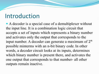
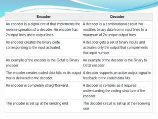
- 2. Introduction ’éŚ A decoder is a special case of a demultiplexer without the input line. It is a combination logic circuit that accepts a set of inputs which represents a binary number and activates only the output that corresponds to the input number. A decoder can generate a maximum of 2Øæø possible minterms with an n-bit binary code. In other words, a decoder circuit looks at its inputs, determines which binary number is present there, and activates the one output that corresponds to that number- all other outputs remain inactive.
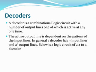
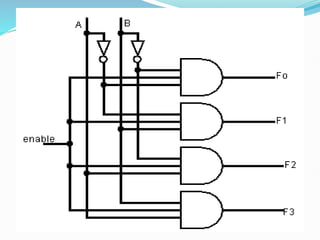
- 3. Decoders ’éŚ A decoder is a combinational logic circuit with a number of output lines one of which is active at any one time. ’éŚ The active output line is dependent on the pattern of the input lines. In general a decoder has n input lines and 2n output lines. Below is a logic circuit of a 2 to 4 decoder.
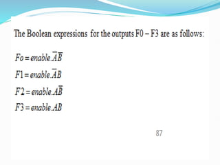
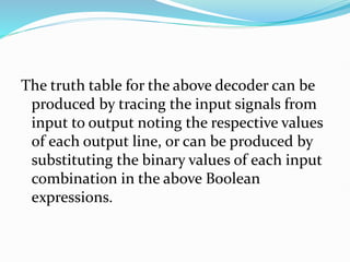
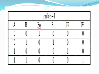
- 6. The truth table for the above decoder can be produced by tracing the input signals from input to output noting the respective values of each output line, or can be produced by substituting the binary values of each input combination in the above Boolean expressions.
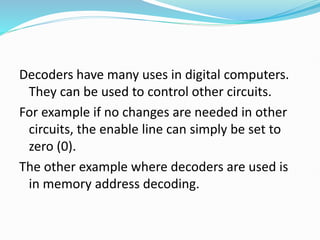
- 8. Decoders have many uses in digital computers. They can be used to control other circuits. For example if no changes are needed in other circuits, the enable line can simply be set to zero (0). The other example where decoders are used is in memory address decoding.
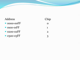
- 9. Address Chip ’éŚ 0000-00FF 0 ’éŚ 0100-01FF 1 ’éŚ 0200-02FF 2 ’éŚ 0300-03FF 3
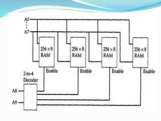
- 10. So each chip requires eight (8) address lines and these are supplied by the bits 0- 7 bit lines. The higher- order 2 bits, 8 and 9 are used to select one of the four chips by using the 2 to 4 decoder. The outputs of the decoder enable only one of the four chips at a time.
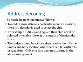
- 12. Address decoding The block diagram operates as follows: ’éŚ To read or store data to a particular memory location, the 2 to 4 decoder is used to select the chip. ’éŚ For example if A8 = 0 and A9 = 0 then chip 0 will be selected by enable line 0 at the output of the decoder to a 1. ’éŚ The address lines A0 ŌĆōA7 are then used to identify the unique memory location where data can be written to or read from. Only one chip operate at a time in the above arrangement.
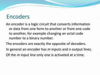
- 13. Encoders An encoder is a logic circuit that converts information or data from one form to another or from one code to another, for example changing an octal code number to a binary number. The encoders are exactly the opposite of decoders. In general an encoder has m inputs and n output lines. Of the m input line only one is activated at a time.
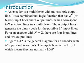
- 14. Introduction ’éŚ An encoder is a multiplexer without its single output line. It is a combinational logic function that has 2Øæü (or fewer) input lines and Øæø output lines, which correspond toØæü selection lines in a multiplexer. The Øæø output lines generate the binary code for the possible 2Øæü input lines. For a an encoder with Øæü = 2, there are four input lines and two output lines. ’éŚ Figure 4-12 is the general diagram for an encoder with ØæĆ inputs and Øæü outputs. The inputs here active HIGH, which means they are normally LOW.
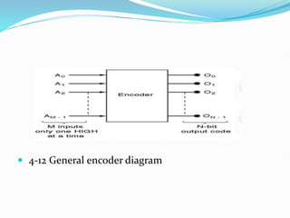
- 15. ’éŚ 4-12 General encoder diagram
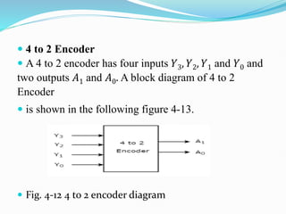
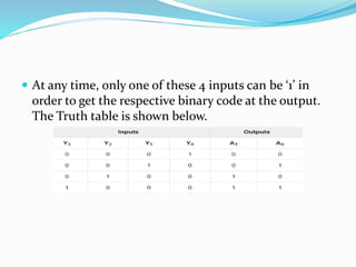
- 16. ’éŚ 4 to 2 Encoder ’éŚ A 4 to 2 encoder has four inputs Øæī3, Øæī2, Øæī1 and Øæī0 and two outputs ØÉ┤1 and ØÉ┤0. A block diagram of 4 to 2 Encoder ’éŚ is shown in the following figure 4-13. ’éŚ Fig. 4-12 4 to 2 encoder diagram
- 17. ’éŚ At any time, only one of these 4 inputs can be ŌĆś1ŌĆÖ in order to get the respective binary code at the output. The Truth table is shown below.
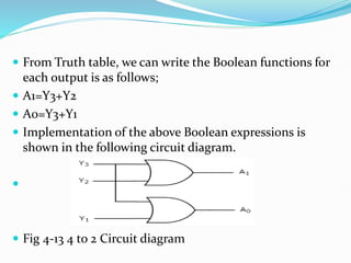
- 18. ’éŚ From Truth table, we can write the Boolean functions for each output is as follows; ’éŚ A1=Y3+Y2 ’éŚ A0=Y3+Y1 ’éŚ Implementation of the above Boolean expressions is shown in the following circuit diagram. ’éŚ ’éŚ Fig 4-13 4 to 2 Circuit diagram
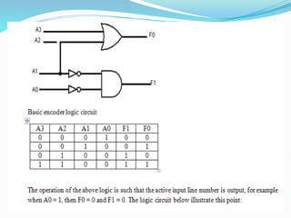
- 19. Encoders can also be used for security (data inscription) and saving memory space (data compression). An example of a basic encoder logic circuit is shown below:
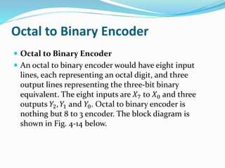
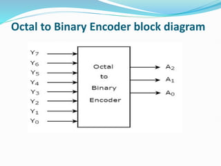
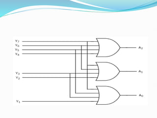
- 21. Octal to Binary Encoder ’éŚ Octal to Binary Encoder ’éŚ An octal to binary encoder would have eight input lines, each representing an octal digit, and three output lines representing the three-bit binary equivalent. The eight inputs are Øæŗ7 to Øæŗ0 and three outputs Øæī2, Øæī1 and Øæī0. Octal to binary encoder is nothing but 8 to 3 encoder. The block diagram is shown in Fig. 4-14 below.
- 22. Octal to Binary Encoder block diagram
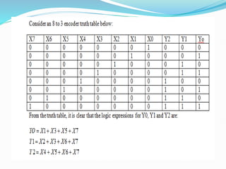
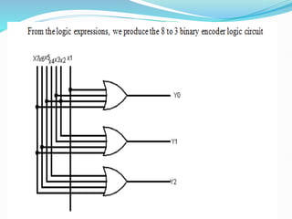
- 26. ’éŚ The eight input lines would have 28 = 256 possible combinations. However, in the case of an octal-to- binary encoder, only eight of these 256 combinations would have any meaning. The remaining combinations of input variables are ŌĆśØææØæ£ØæøŌĆÖØæĪ ØæÉØæÄØæ¤ØæÆŌĆÖ input combinations. Also, only one of the input lines at a time is in logic ŌĆś1ŌĆÖ state.
- 27. Disadvantages of an encoder ’éŚ There is an ambiguity, when all outputs of encoder are equal to zero. Because, it could be the code corresponding to the inputs, when only least significant input is one or when all inputs are zero. ’éŚ If more than one input is active High, then the encoder produces an output, which may not be the correct code. For example, if both Øæī3 and Øæī6 are ŌĆś1ŌĆÖ, then the encoder produces 111 at the output. This is neither equivalent code corresponding to Øæī3, when it is ŌĆś1ŌĆÖ nor the equivalent code corresponding to Øæī6, when it is ŌĆś1ŌĆÖ.
- 28. ’éŚ So, to overcome these difficulties, we should assign priorities to each input of encoder. Then, the output of encoder will be the binary code corresponding to the active HIGH inputs, which has higher priority. The encoder is known as priority encoder. ’éŚ When more than one input is simultaneously active, the input with the highest priority is encoded.