際際滷

際際滷Share a Scribd company logo
Thermoelastic stress analysis (TSA) is based on volumetric changes of materials under load. When a material
(solid or gas) is compressed or expanded its temperature changes. This process is reversible in that when the load
causing the volumetric change is removed the material goes back to its original temperature and shape (assuming
elastic material behavior and relatively rapid loading changes that eliminate significant conduction of heat).
The temperature changes that need to be measured for TSA are small, on the order of 0.001C (often referred to as
1mK). The change in temperature is proportional to the sum of the principal stresses (the first stress invariant).
The formula that describes the relationship between temperature change and stress change is
where a is the coefficient of thermal expansion, T is the ambient absolute temperature, r is density, and Cp is heat
capacity at constant pressure.
The Conundrum
Failure criteria are not based on the sum of the principal stresses, although, experience indicates that TSA is a good
predictor of failure location and load. How can we reconcile this apparent contradiction?
Failure Theory
Failure criteria are used in combination with information about stresses in a structure to predict the load levels a
structure can withstand. For instance, the Maximum Shear Stress criteria predicts failure (usually plastic yielding
in ductile materials) when the shear stress in a structure reaches some maximum. The value of the failure criteria at
the time a structure fails can be thought of as,
Table 1. Failure Criteria Applicability
or actually is, a material property. There are a number of failure theories for structures. The most commonly used
ones are maximum stress, maximum shear stress, and von Mises stress. Each of these has their applicability, but
the von Mises criteria is considered the most generally applicable.
Table 2. TSA and Failure Criteria Formulas
Finite Element Analysis
Finite element analysis is a numerical modeling technique that combines structural geometry and loading
information with material properties to predict stresses and strains in a structure. The technique is quite flexible
and has wide applicability. FEA is often effectively used early in the design cycle to provide important information
by reporting stresses in a structure full-field.
However, FEA has some short comings. Modeling some particular, yet fairly common, types of loads and
structural components with enough detail to provide good predictions can be difficult, and FEA is susceptible to
incorrect information about material properties and loading conditions. Consequently, FEA is often used in
combination with an experimental technique or some other confirming information.
Failure Prediction with FEA and TSA
Since finite element analysis (FEA) and thermoelastic stress analysis (TSA) are both full-field techniques it is also
useful to think of failure criteria in full-field terms.
Consider an image of the stresses near a hole in a strap loaded in pure tension for each of the formulations shown
in Table 2. There are places around the hole where the stress state is biaxial, so it is expected that full-field
presentations for each of the formulations would be different.
One difference between the presentations would be the availability of sign information (see Table 3.). The sign is
useful information to the stress analyst trying to visualize the stress flow through a structure. One could argue that
shear stress has sign but it is not useful to think of it in this way. In terms of Mohr's circle shear stress is the
diameter of the Mohr's circle, but a diameter cannot have a negative value.
Table 3. Full-Field Sign Information
When Failure Theories Converge
To look at the situation from another angle, consider that many cracks start on an edge of a structure. Fig. 1
describes the stress state at an edge. No stress is present in two perpendicular directions because they are open to
the air. (Of course, this is not always true, the example of a round shaft can be sighted, but bear with me.) For this
important state of stress all three failure criteria, and the sum of the principal stresses reduce to the same thing, s1.
Therefore the stress concentration factor, Kt that is calculated by all the formulas is the same at the critical failure
location.
Fig. 3. State of stress near an edge must be uniaxial.
Table 4. Calculating Kt with each of the formulas for the
state of stress at the edge of a hole in a tensile field.
The Case of Pure Shear
Consider the most common case of pure shear stress, a uniform bar in torsion. Pure shear stress causes a material
to shear only. Since there is no volumetric change, the sum of the principal stresses is zero. Consequently, TSA is
often discounted as a useful measurement on this basis.
As a practical matter there are few times when the section of shaft in pure shear is of interest structurally. This is
because it is easy to calculate the stress levels in a shaft, failure theory holds well and consequently the design is
usually well executed. The torque input and output couplings, however, are the likely causes of problems. Splines,
keyways, shear pins, tapers, fillets, or notches are generally where problem initiate. In all of these cases the state of
stress is a complicated one. One that challenges every experimental, numerical, and analytical technique. In
difficult circumstances any information is welcome. Under circumstances like these FEA and TSA can work well
together to solve problems.
TSA and FEA
One of the most common uses of TSA is the confirmation and fine tuning of FEA models. The techniques have
much in common, or maybe it is better to say " in complement". Both techniques are full-field. Both techniques
have a spatial resolution dependent on the size of element (pixel) used. Both techniques are strong at showing
relative stress in a structure in terms of location and magnitude. Both techniques require loading information and
material property information for the accurate prediction of failure location and probability. For all their
similarities, it is the differences that make the two techniques particularly strong when used together. FEA is most
often used early in the design cycle. It is very useful in comparing design alternatives, but only if the model is
accurate. If a prototype is available, even a plastic model, TSA can be used to confirm that the FEA model is
accurate.
While TSA requires the actual application of loads to the structure, this can bring into focus aspects of loading that
are very difficult to predict or model. TSA of an actual prototype will not give false readings because of poor
meshing, element choice, or inaccurate geometry modeling. Once confidence in the FEA model is established it
can be used to check internal stresses, and to test design modifications without actually needing to be test a
specimen.
Sometimes structures are very complicated, or loading on the structure is so complicated that FEA is presented
with nearly insurmountable challenges for a detailed analysis. Consider a highway bridge, where traffic loading,
redundant supports, and interactions between concrete and steel set out a very difficult problem. Consider the fuel
tank of a car, which is a complicated shape loaded with vibrations and road inputs, and filled with an infinite
number of possible fuel levels. FEA is hardly useless in these cases, but only if loading inputs or initial stress
states, or particular stress states can be verified. TSA will provide a stress pattern for any given condition, and it
will always be the right stress pattern for that condition. By using TSA data as a starting point designers
experiment with either real or numerical methods to see how structural conditions can be optimized.
In Terms of Mohr's Circle
Many failure theories are discussed in terms of Mohr's circle. The TSA measurement provides the sum of the
principal stresses. Divide this by two and you have the location of the center of the Mohr's circle on the s axis.
Photoelasticity results are proportional to the difference of the principal stresses, which is the diameter of Mohr's
circle. (We gotta get these two together.) The full triaxial state of stress at any point can be represented as three
circles. Compatibility dictates that each of the three circles must touch the other two along the s axis. The state of
stress at the surface of a structure can only have a biaxial state of stress. In this case two of the three circles must
go through the origin.
Conclusion
Like every experimental, numerical, and analytical stress analysis technique TSA has its advantages and
disadvantages. We believe that an informed user of TSA technology can obtain interesting and useful results.
The engineers at Stress Photonics are always interested in discussing applications of TSA and other experimental
techniques. We know that helping our customers (and potential customers) find effective and appropriate solutions
to their problems must be our primary goal. We continue to develop the TSA technology so that it can be a tool to
help solve an increasingly broader range of engineering problems.
Fig 2. TSA image of stress near a hole in a strap loaded in tension.

More Related Content

Viewers also liked (19)

Thirsty
ThirstyThirsty
Thirsty
justinbrown01
1
11
1
saajidt
No v knji転nici
No v knji転niciNo v knji転nici
No v knji転nici
Nena Mandelj
05 Drillers Method
05 Drillers Method05 Drillers Method
05 Drillers Method
Stan Herring
Loracwynaroctober29
Loracwynaroctober29Loracwynaroctober29
Loracwynaroctober29
lcwynar
oopnew
oopnewoopnew
oopnew
Phannida Panyasit
Vida Despues De la VidaVida Despues De la Vida
Vida Despues De la Vida
Daniel J Alejos C
Ministerio del Tiempo.Misi坦n Revoluci坦n FrancesaMinisterio del Tiempo.Misi坦n Revoluci坦n Francesa
Ministerio del Tiempo.Misi坦n Revoluci坦n Francesa
Geohistoria23
Bcn Cool Hunter newsletter 10Bcn Cool Hunter newsletter 10
Bcn Cool Hunter newsletter 10
Dafne Patruno
The life of an entrepreneur - by me
The life of an entrepreneur - by meThe life of an entrepreneur - by me
The life of an entrepreneur - by me
Jasper Goyvaerts
Multiplying polynomial
Multiplying polynomialMultiplying polynomial
Multiplying polynomial
40362746
What is Life?
What is Life?What is Life?
What is Life?
Keaton Cutler
Bahan berbahaya dan beracun
Bahan berbahaya dan beracunBahan berbahaya dan beracun
Bahan berbahaya dan beracun
trilangga.com
Software Architecture for Automated Fault Analysis: Scalable Deployment and U...
Software Architecture for Automated Fault Analysis: Scalable Deployment and U...Software Architecture for Automated Fault Analysis: Scalable Deployment and U...
Software Architecture for Automated Fault Analysis: Scalable Deployment and U...
Tomo Popovic
5. no v 邸olski knji転nici O Litija/Night in the school library
5. no v 邸olski knji転nici O Litija/Night in the school library 5. no v 邸olski knji転nici O Litija/Night in the school library
5. no v 邸olski knji転nici O Litija/Night in the school library
Nena Mandelj
Disorganization Schalonia Smith
Disorganization Schalonia SmithDisorganization Schalonia Smith
Disorganization Schalonia Smith
cheloina
Using Symbols
Using SymbolsUsing Symbols
Using Symbols
Myamor Estrella
No v knji転nici
No v knji転niciNo v knji転nici
No v knji転nici
Nena Mandelj
05 Drillers Method
05 Drillers Method05 Drillers Method
05 Drillers Method
Stan Herring
Loracwynaroctober29
Loracwynaroctober29Loracwynaroctober29
Loracwynaroctober29
lcwynar
Vida Despues De la VidaVida Despues De la Vida
Vida Despues De la Vida
Daniel J Alejos C
Ministerio del Tiempo.Misi坦n Revoluci坦n FrancesaMinisterio del Tiempo.Misi坦n Revoluci坦n Francesa
Ministerio del Tiempo.Misi坦n Revoluci坦n Francesa
Geohistoria23
Bcn Cool Hunter newsletter 10Bcn Cool Hunter newsletter 10
Bcn Cool Hunter newsletter 10
Dafne Patruno
The life of an entrepreneur - by me
The life of an entrepreneur - by meThe life of an entrepreneur - by me
The life of an entrepreneur - by me
Jasper Goyvaerts
Multiplying polynomial
Multiplying polynomialMultiplying polynomial
Multiplying polynomial
40362746
Bahan berbahaya dan beracun
Bahan berbahaya dan beracunBahan berbahaya dan beracun
Bahan berbahaya dan beracun
trilangga.com
Software Architecture for Automated Fault Analysis: Scalable Deployment and U...
Software Architecture for Automated Fault Analysis: Scalable Deployment and U...Software Architecture for Automated Fault Analysis: Scalable Deployment and U...
Software Architecture for Automated Fault Analysis: Scalable Deployment and U...
Tomo Popovic
5. no v 邸olski knji転nici O Litija/Night in the school library
5. no v 邸olski knji転nici O Litija/Night in the school library 5. no v 邸olski knji転nici O Litija/Night in the school library
5. no v 邸olski knji転nici O Litija/Night in the school library
Nena Mandelj
Disorganization Schalonia Smith
Disorganization Schalonia SmithDisorganization Schalonia Smith
Disorganization Schalonia Smith
cheloina

Similar to Lecture failure criteria (20)

Tom&md notes module 03
Tom&md notes module 03Tom&md notes module 03
Tom&md notes module 03
Ashish Mishra
d_9_special-topics-project_FEA-of-full-assemblies
d_9_special-topics-project_FEA-of-full-assembliesd_9_special-topics-project_FEA-of-full-assemblies
d_9_special-topics-project_FEA-of-full-assemblies
mike siener
lecturenote_1177425455CAPTER TWO-Design for static strength.pdf
lecturenote_1177425455CAPTER TWO-Design for static strength.pdflecturenote_1177425455CAPTER TWO-Design for static strength.pdf
lecturenote_1177425455CAPTER TWO-Design for static strength.pdf
Praveen Kumar
Tensile
TensileTensile
Tensile
Ammour Omrane
Mech CE6306 som_notes
Mech CE6306 som_notesMech CE6306 som_notes
Mech CE6306 som_notes
KIT-Kalaignar Karunanidhi Institute of Technology
Composites-Final-Report-no.-2
Composites-Final-Report-no.-2Composites-Final-Report-no.-2
Composites-Final-Report-no.-2
Arya dash
Senior Project Report
Senior Project Report Senior Project Report
Senior Project Report
Francisco Davila
Unit 1 notes-final
Unit 1 notes-finalUnit 1 notes-final
Unit 1 notes-final
jagadish108
Pressure Vessel Design Manual-STRESS.pdf
Pressure Vessel Design Manual-STRESS.pdfPressure Vessel Design Manual-STRESS.pdf
Pressure Vessel Design Manual-STRESS.pdf
niteshkumar293686
Stress strain curve
Stress strain curveStress strain curve
Stress strain curve
Mazadul Hasan
Hq2413531358
Hq2413531358Hq2413531358
Hq2413531358
IJERA Editor
LNm7.pdf
LNm7.pdfLNm7.pdf
LNm7.pdf
Dhanesh32
Arellano bond
Arellano bondArellano bond
Arellano bond
Nghi棚n C畛u 畛nh L動畛ng
UNIT-I-Theories of failures-19072016.pptx
UNIT-I-Theories of failures-19072016.pptxUNIT-I-Theories of failures-19072016.pptx
UNIT-I-Theories of failures-19072016.pptx
Praveen Kumar
Paper id 71201964
Paper id 71201964Paper id 71201964
Paper id 71201964
IJRAT
Truss Engineering
Truss Engineering Truss Engineering
Truss Engineering
rawaabdullah
Modelling and Analysis Laboratory Manual
Modelling and Analysis Laboratory ManualModelling and Analysis Laboratory Manual
Modelling and Analysis Laboratory Manual
Hareesha N Gowda, Dayananda Sagar College of Engg, Bangalore
Evaluation of Engineering Stresses as the Correct Measure of Physical Str...
Evaluation of Engineering Stresses as the Correct Measure of Physical Str...Evaluation of Engineering Stresses as the Correct Measure of Physical Str...
Evaluation of Engineering Stresses as the Correct Measure of Physical Str...
International Journal of Engineering Inventions www.ijeijournal.com
Thesis - Design a Planar Simple Shear Test for Characterizing Large Strange B...
Thesis - Design a Planar Simple Shear Test for Characterizing Large Strange B...Thesis - Design a Planar Simple Shear Test for Characterizing Large Strange B...
Thesis - Design a Planar Simple Shear Test for Characterizing Large Strange B...
Marshal Fulford
Ch06 introduction to_static_failure_theories
Ch06 introduction to_static_failure_theoriesCh06 introduction to_static_failure_theories
Ch06 introduction to_static_failure_theories
Paralafakyou Mens
Tom&md notes module 03
Tom&md notes module 03Tom&md notes module 03
Tom&md notes module 03
Ashish Mishra
d_9_special-topics-project_FEA-of-full-assemblies
d_9_special-topics-project_FEA-of-full-assembliesd_9_special-topics-project_FEA-of-full-assemblies
d_9_special-topics-project_FEA-of-full-assemblies
mike siener
lecturenote_1177425455CAPTER TWO-Design for static strength.pdf
lecturenote_1177425455CAPTER TWO-Design for static strength.pdflecturenote_1177425455CAPTER TWO-Design for static strength.pdf
lecturenote_1177425455CAPTER TWO-Design for static strength.pdf
Praveen Kumar
Composites-Final-Report-no.-2
Composites-Final-Report-no.-2Composites-Final-Report-no.-2
Composites-Final-Report-no.-2
Arya dash
Unit 1 notes-final
Unit 1 notes-finalUnit 1 notes-final
Unit 1 notes-final
jagadish108
Pressure Vessel Design Manual-STRESS.pdf
Pressure Vessel Design Manual-STRESS.pdfPressure Vessel Design Manual-STRESS.pdf
Pressure Vessel Design Manual-STRESS.pdf
niteshkumar293686
Stress strain curve
Stress strain curveStress strain curve
Stress strain curve
Mazadul Hasan
UNIT-I-Theories of failures-19072016.pptx
UNIT-I-Theories of failures-19072016.pptxUNIT-I-Theories of failures-19072016.pptx
UNIT-I-Theories of failures-19072016.pptx
Praveen Kumar
Paper id 71201964
Paper id 71201964Paper id 71201964
Paper id 71201964
IJRAT
Truss Engineering
Truss Engineering Truss Engineering
Truss Engineering
rawaabdullah
Thesis - Design a Planar Simple Shear Test for Characterizing Large Strange B...
Thesis - Design a Planar Simple Shear Test for Characterizing Large Strange B...Thesis - Design a Planar Simple Shear Test for Characterizing Large Strange B...
Thesis - Design a Planar Simple Shear Test for Characterizing Large Strange B...
Marshal Fulford
Ch06 introduction to_static_failure_theories
Ch06 introduction to_static_failure_theoriesCh06 introduction to_static_failure_theories
Ch06 introduction to_static_failure_theories
Paralafakyou Mens

More from Hamdani Nurdin (6)

Chapter i
Chapter iChapter i
Chapter i
Hamdani Nurdin
Belajar pemrograman
Belajar pemrogramanBelajar pemrograman
Belajar pemrograman
Hamdani Nurdin
Csis 1514 excel ch 1 ppt
Csis 1514 excel ch 1 pptCsis 1514 excel ch 1 ppt
Csis 1514 excel ch 1 ppt
Hamdani Nurdin
Caramembuat website sederhana
Caramembuat website sederhanaCaramembuat website sederhana
Caramembuat website sederhana
Hamdani Nurdin
Journal predicting of plastic ratcheting of cylinder subjected to axial mov...
Journal   predicting of plastic ratcheting of cylinder subjected to axial mov...Journal   predicting of plastic ratcheting of cylinder subjected to axial mov...
Journal predicting of plastic ratcheting of cylinder subjected to axial mov...
Hamdani Nurdin
Lecture equivalent plastic strain
Lecture   equivalent plastic strainLecture   equivalent plastic strain
Lecture equivalent plastic strain
Hamdani Nurdin
Belajar pemrograman
Belajar pemrogramanBelajar pemrograman
Belajar pemrograman
Hamdani Nurdin
Csis 1514 excel ch 1 ppt
Csis 1514 excel ch 1 pptCsis 1514 excel ch 1 ppt
Csis 1514 excel ch 1 ppt
Hamdani Nurdin
Caramembuat website sederhana
Caramembuat website sederhanaCaramembuat website sederhana
Caramembuat website sederhana
Hamdani Nurdin
Journal predicting of plastic ratcheting of cylinder subjected to axial mov...
Journal   predicting of plastic ratcheting of cylinder subjected to axial mov...Journal   predicting of plastic ratcheting of cylinder subjected to axial mov...
Journal predicting of plastic ratcheting of cylinder subjected to axial mov...
Hamdani Nurdin
Lecture equivalent plastic strain
Lecture   equivalent plastic strainLecture   equivalent plastic strain
Lecture equivalent plastic strain
Hamdani Nurdin

Lecture failure criteria

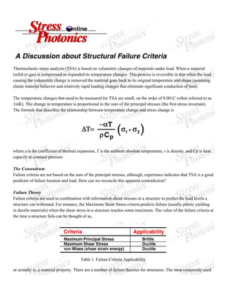
  • 1. Thermoelastic stress analysis (TSA) is based on volumetric changes of materials under load. When a material (solid or gas) is compressed or expanded its temperature changes. This process is reversible in that when the load causing the volumetric change is removed the material goes back to its original temperature and shape (assuming elastic material behavior and relatively rapid loading changes that eliminate significant conduction of heat). The temperature changes that need to be measured for TSA are small, on the order of 0.001C (often referred to as 1mK). The change in temperature is proportional to the sum of the principal stresses (the first stress invariant). The formula that describes the relationship between temperature change and stress change is where a is the coefficient of thermal expansion, T is the ambient absolute temperature, r is density, and Cp is heat capacity at constant pressure. The Conundrum Failure criteria are not based on the sum of the principal stresses, although, experience indicates that TSA is a good predictor of failure location and load. How can we reconcile this apparent contradiction? Failure Theory Failure criteria are used in combination with information about stresses in a structure to predict the load levels a structure can withstand. For instance, the Maximum Shear Stress criteria predicts failure (usually plastic yielding in ductile materials) when the shear stress in a structure reaches some maximum. The value of the failure criteria at the time a structure fails can be thought of as, Table 1. Failure Criteria Applicability or actually is, a material property. There are a number of failure theories for structures. The most commonly used
  • 2. ones are maximum stress, maximum shear stress, and von Mises stress. Each of these has their applicability, but the von Mises criteria is considered the most generally applicable. Table 2. TSA and Failure Criteria Formulas Finite Element Analysis Finite element analysis is a numerical modeling technique that combines structural geometry and loading information with material properties to predict stresses and strains in a structure. The technique is quite flexible and has wide applicability. FEA is often effectively used early in the design cycle to provide important information by reporting stresses in a structure full-field. However, FEA has some short comings. Modeling some particular, yet fairly common, types of loads and structural components with enough detail to provide good predictions can be difficult, and FEA is susceptible to incorrect information about material properties and loading conditions. Consequently, FEA is often used in combination with an experimental technique or some other confirming information. Failure Prediction with FEA and TSA Since finite element analysis (FEA) and thermoelastic stress analysis (TSA) are both full-field techniques it is also useful to think of failure criteria in full-field terms. Consider an image of the stresses near a hole in a strap loaded in pure tension for each of the formulations shown in Table 2. There are places around the hole where the stress state is biaxial, so it is expected that full-field presentations for each of the formulations would be different. One difference between the presentations would be the availability of sign information (see Table 3.). The sign is useful information to the stress analyst trying to visualize the stress flow through a structure. One could argue that shear stress has sign but it is not useful to think of it in this way. In terms of Mohr's circle shear stress is the diameter of the Mohr's circle, but a diameter cannot have a negative value.
  • 3. Table 3. Full-Field Sign Information When Failure Theories Converge To look at the situation from another angle, consider that many cracks start on an edge of a structure. Fig. 1 describes the stress state at an edge. No stress is present in two perpendicular directions because they are open to the air. (Of course, this is not always true, the example of a round shaft can be sighted, but bear with me.) For this important state of stress all three failure criteria, and the sum of the principal stresses reduce to the same thing, s1. Therefore the stress concentration factor, Kt that is calculated by all the formulas is the same at the critical failure location. Fig. 3. State of stress near an edge must be uniaxial. Table 4. Calculating Kt with each of the formulas for the state of stress at the edge of a hole in a tensile field. The Case of Pure Shear Consider the most common case of pure shear stress, a uniform bar in torsion. Pure shear stress causes a material to shear only. Since there is no volumetric change, the sum of the principal stresses is zero. Consequently, TSA is often discounted as a useful measurement on this basis. As a practical matter there are few times when the section of shaft in pure shear is of interest structurally. This is because it is easy to calculate the stress levels in a shaft, failure theory holds well and consequently the design is usually well executed. The torque input and output couplings, however, are the likely causes of problems. Splines, keyways, shear pins, tapers, fillets, or notches are generally where problem initiate. In all of these cases the state of stress is a complicated one. One that challenges every experimental, numerical, and analytical technique. In difficult circumstances any information is welcome. Under circumstances like these FEA and TSA can work well
  • 4. together to solve problems. TSA and FEA One of the most common uses of TSA is the confirmation and fine tuning of FEA models. The techniques have much in common, or maybe it is better to say " in complement". Both techniques are full-field. Both techniques have a spatial resolution dependent on the size of element (pixel) used. Both techniques are strong at showing relative stress in a structure in terms of location and magnitude. Both techniques require loading information and material property information for the accurate prediction of failure location and probability. For all their similarities, it is the differences that make the two techniques particularly strong when used together. FEA is most often used early in the design cycle. It is very useful in comparing design alternatives, but only if the model is accurate. If a prototype is available, even a plastic model, TSA can be used to confirm that the FEA model is accurate. While TSA requires the actual application of loads to the structure, this can bring into focus aspects of loading that are very difficult to predict or model. TSA of an actual prototype will not give false readings because of poor meshing, element choice, or inaccurate geometry modeling. Once confidence in the FEA model is established it can be used to check internal stresses, and to test design modifications without actually needing to be test a specimen. Sometimes structures are very complicated, or loading on the structure is so complicated that FEA is presented with nearly insurmountable challenges for a detailed analysis. Consider a highway bridge, where traffic loading, redundant supports, and interactions between concrete and steel set out a very difficult problem. Consider the fuel tank of a car, which is a complicated shape loaded with vibrations and road inputs, and filled with an infinite number of possible fuel levels. FEA is hardly useless in these cases, but only if loading inputs or initial stress states, or particular stress states can be verified. TSA will provide a stress pattern for any given condition, and it will always be the right stress pattern for that condition. By using TSA data as a starting point designers experiment with either real or numerical methods to see how structural conditions can be optimized. In Terms of Mohr's Circle Many failure theories are discussed in terms of Mohr's circle. The TSA measurement provides the sum of the principal stresses. Divide this by two and you have the location of the center of the Mohr's circle on the s axis. Photoelasticity results are proportional to the difference of the principal stresses, which is the diameter of Mohr's circle. (We gotta get these two together.) The full triaxial state of stress at any point can be represented as three circles. Compatibility dictates that each of the three circles must touch the other two along the s axis. The state of stress at the surface of a structure can only have a biaxial state of stress. In this case two of the three circles must go through the origin. Conclusion Like every experimental, numerical, and analytical stress analysis technique TSA has its advantages and disadvantages. We believe that an informed user of TSA technology can obtain interesting and useful results.
  • 5. The engineers at Stress Photonics are always interested in discussing applications of TSA and other experimental techniques. We know that helping our customers (and potential customers) find effective and appropriate solutions to their problems must be our primary goal. We continue to develop the TSA technology so that it can be a tool to help solve an increasingly broader range of engineering problems. Fig 2. TSA image of stress near a hole in a strap loaded in tension.