

![MACHINE INSTRUCTION FORMAT
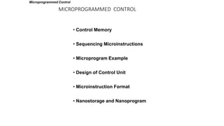
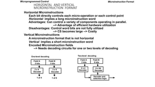
Microinstruction Format for control memory with 20 bits, divided into 4 functional parts , F1,F2,F3 ŌĆō specify
microoperations, CD ŌĆō status bit for conditions, BR type of branch, AD branch address 7 bit
Microprogram
EA is the effective address
Symbol OP-code Description
ADD 0000 AC ’é¼ AC + M[EA]
BRANCH 0001 if (AC < 0) then (PC ’é¼ EA)
STORE 0010 M[EA] ’é¼ AC
EXCHANGE 0011 AC ’é¼ M[EA], M[EA] ’é¼ AC
Machine instruction format : one bit for indirect addressing, 4 bits for opcode, 11 bits for address
I Opcode
15 14 11 10
Address
0
Sample machine instructions :
4 sample instructions out of 16 distinct possible instructions
F1 F2 F3 CD BR AD
3 3 3 2 2 7
F1, F2, F3: Microoperation fields
CD: Condition for branching
BR: Branch field
AD: Address field
Microprogrammed Control](https://image.slidesharecdn.com/microprogrammedcontrol-3-221129144221-b3926404/85/MICROPROGRAMMEDCONTROL-3-pptx-12-320.jpg)
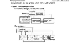
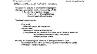
![MICROINSTRUCTION FIELD DESCRIPTIONS - F1,F2,F3
F1 Microoperation Symbol
000 None NOP
001 AC ’é¼ AC + DR ADD
010 AC ’é¼ 0 CLRAC
011 AC ’é¼ AC + 1 INCAC
100 AC ’é¼ DR DRTAC
101 AR ’é¼ DR(0-10) DRTAR
110 AR ’é¼ PC PCTAR
111 M[AR] ’é¼ DR WRITE
Microprogram
F2 Microoperation Symbol
000 None NOP
001 AC ’é¼ AC - DR SUB
010 AC ’é¼ AC ’āÜ DR OR
011 AC ’é¼ AC ’āÖ DR AND
100 DR ’é¼ M[AR] READ
101 DR ’é¼ AC ACTDR
110 DR ’é¼ DR + 1 INCDR
111 DR(0-10) ’é¼ PC PCTDR
F3 Microoperation Symbol
000 None NOP
001 AC ’é¼ AC ’āģ DR XOR
010 AC ’é¼ ACŌĆÖ COM
011 AC ’é¼ shl AC SHL
100 AC ’é¼ shr AC SHR
101 PC ’é¼ PC + 1 INCPC
110 PC ’é¼ AR ARTPC
111 Reserved
Microprogrammed Control
Microoperations are subdivided into 3 fields each 3 bits gives total 21 operations. A micro instruction can choose no
more than 3 operation one from each field. If less than 3 instructions are used then the binary code 000 is used for no
operation for either of the fields.
For example a micro instruction for 9 bits 000 100 101
as follows
DR ’ā¤ M[AR] F2=100
PC <- PC + 1 F3=101](https://image.slidesharecdn.com/microprogrammedcontrol-3-221129144221-b3926404/85/MICROPROGRAMMEDCONTROL-3-pptx-13-320.jpg)
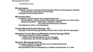
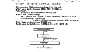
![SYMBOLIC MICROPROGRAM - FETCH ROUTINE
AR ’é¼ PC
DR ’é¼ M[AR], PC ’é¼ PC + 1
AR ’é¼ DR(0-10), CAR(2-5) ’é¼ DR(11-14), CAR(0,1,6) ’é¼ 0
Symbolic microprogram for the fetch cycle:
ORG 64
PCTAR U JMP NEXT
READ, INCPC U JMP NEXT
DRTAR U MAP
FETCH:
Binary equivalents translated by an assembler
1000000 110 000 000 00 00 1000001
1000001 000 100 101 00 00 1000010
1000010 101 000 000 00 11 0000000
Binary
address F1 F2 F3 CD BR AD
Microprogram
During FETCH, Read an instruction from memory
and decode the instruction and update PC
Sequence of microoperations in the fetch cycle:
Microprogrammed Control](https://image.slidesharecdn.com/microprogrammedcontrol-3-221129144221-b3926404/85/MICROPROGRAMMEDCONTROL-3-pptx-16-320.jpg)


More Related Content
Similar to MICROPROGRAMMEDCONTROL-3.pptx (20)
Recently uploaded (20)


MICROPROGRAMMEDCONTROL-3.pptx
- 2. MICROPROGRAMMED CONTROL ŌĆó Control Memory ŌĆó Sequencing Microinstructions ŌĆó Microprogram Example ŌĆó Design of Control Unit ŌĆó Microinstruction Format ŌĆó Nanostorage and Nanoprogram Microprogrammed Control
- 3. COMPARISON OF CONTROL UNIT IMPLEMENTATIONS Implementation of Control Unit Control Unit Implementation Combinational Logic Circuits (Hard-wired) Microprogram I R Status F/Fs Control Data Combinational Logic Circuits Control Points CPU Memory Timing State Ins. Cycle State Control Unit's State Status F/Fs Control Data Next Address Generation Logic C S A R Control Storage (’üŁ-program memory) M e m o r y I R C S D R C P s CPU D } Microprogrammed Control
- 4. TERMINOLOGY Microprogram - Program stored in memory that generates all the control signals required to execute the instruction set correctly - Consists of microinstructions Microinstruction - Contains a control word and a sequencing word Control Word - All the control information required for one clock cycle Sequencing Word - Information needed to decide the next microinstruction address - Vocabulary to write a microprogram Control Memory(Control Storage: CS) - Storage in the microprogrammed control unit to store the microprogram Writeable Control Memory(Writeable Control Storage:WCS) - CS whose contents can be modified -> Allows the microprogram can be changed -> Instruction set can be changed or modified Dynamic Microprogramming - Computer system whose control unit is implemented with a microprogram in WCS - Microprogram can be changed by a systems programmer or a user Microprogrammed Control
- 5. TERMINOLOGY Sequencer (Microprogram Sequencer) A Microprogram Control Unit that determines the Microinstruction Address to be executed in the next clock cycle - In-line Sequencing - Branch - Conditional Branch - Subroutine - Loop - Instruction OP-code mapping Microprogrammed Control
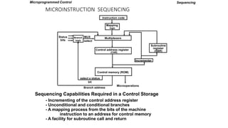
- 6. MICROINSTRUCTION SEQUENCING Sequencing Capabilities Required in a Control Storage - Incrementing of the control address register - Unconditional and conditional branches - A mapping process from the bits of the machine instruction to an address for control memory - A facility for subroutine call and return Sequencing Instruction code Mapping logic Multiplexers Control memory (ROM) Subroutine register (SBR) Branch logic Status bits Microoperations Control address register (CAR) Incrementer MUX select select a status bit Branch address Microprogrammed Control
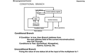
- 7. CONDITIONAL BRANCH Unconditional Branch Fixing the value of one status bit at the input of the multiplexer to 1 Sequencing Conditional Branch If Condition is true, then Branch (address from the next address field of the current microinstruction) else Fall Through Conditions to Test: O(overflow), N(negative), Z(zero), C(carry), etc. Control address register Control memory MUX Load address Increment Status (condition) bits Micro-operations Condition select Next address ... Microprogrammed Control
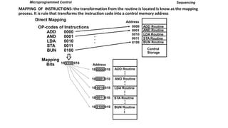
- 8. MAPPING OF INSTRUCTIONS: the transformation from the routine is located is know as the mapping process. It is rule that transforms the instruction code into a control memory address Sequencing ADD Routine AND Routine LDA Routine STA Routine BUN Routine Control Storage 0000 0001 0010 0011 0100 OP-codes of Instructions ADD AND LDA STA BUN 0000 0001 0010 0011 0100 . . . Direct Mapping Address 10 0000 010 10 0001 010 10 0010 010 10 0011 010 10 0100 010 Mapping Bits 10 xxxx 010 ADD Routine Address AND Routine LDA Routine STA Routine BUN Routine Microprogrammed Control
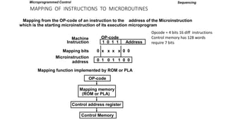
- 9. MAPPING OF INSTRUCTIONS TO MICROROUTINES Mapping function implemented by ROM or PLA OP-code Mapping memory (ROM or PLA) Control address register Control Memory Mapping from the OP-code of an instruction to the address of the Microinstruction which is the starting microinstruction of its execution microprogram 1 0 1 1 Address OP-code Mapping bits Microinstruction address 0 x x x x 0 0 0 1 0 1 1 0 0 Machine Instruction Sequencing Microprogrammed Control Opcode = 4 bits 16 diff instructions Control memory has 128 words require 7 bits
- 10. Subroutine Register : microprograms that uses the subroutine to have a provision for storing the return address during a subroutine call and restoring the address during a subroutine return. This can be done with a subroutine register, is the source for transferring the address for the return to main routine.
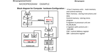
- 11. MICROPROGRAM EXAMPLE Microprogram Block diagram for Computer hardware Configuration : MUX AR 10 0 PC 10 0 Address Memory 2048 x 16 MUX DR 15 0 Arithmetic logic and shift unit AC 15 0 SBR 6 0 CAR 6 0 Control memory 128 x 20 Control unit Microprogrammed Control it has 2 memory units : main memory and control memory Main memory : storing instructions and data Control memory : storing micro program 4 registers in processor unit are PC,DR,AR,AC 2 registers with control unit ŌĆō CAR,SBR CAR : control Address register SBR : subroutine register
- 12. MACHINE INSTRUCTION FORMAT Microinstruction Format for control memory with 20 bits, divided into 4 functional parts , F1,F2,F3 ŌĆō specify microoperations, CD ŌĆō status bit for conditions, BR type of branch, AD branch address 7 bit Microprogram EA is the effective address Symbol OP-code Description ADD 0000 AC ’é¼ AC + M[EA] BRANCH 0001 if (AC < 0) then (PC ’é¼ EA) STORE 0010 M[EA] ’é¼ AC EXCHANGE 0011 AC ’é¼ M[EA], M[EA] ’é¼ AC Machine instruction format : one bit for indirect addressing, 4 bits for opcode, 11 bits for address I Opcode 15 14 11 10 Address 0 Sample machine instructions : 4 sample instructions out of 16 distinct possible instructions F1 F2 F3 CD BR AD 3 3 3 2 2 7 F1, F2, F3: Microoperation fields CD: Condition for branching BR: Branch field AD: Address field Microprogrammed Control
- 13. MICROINSTRUCTION FIELD DESCRIPTIONS - F1,F2,F3 F1 Microoperation Symbol 000 None NOP 001 AC ’é¼ AC + DR ADD 010 AC ’é¼ 0 CLRAC 011 AC ’é¼ AC + 1 INCAC 100 AC ’é¼ DR DRTAC 101 AR ’é¼ DR(0-10) DRTAR 110 AR ’é¼ PC PCTAR 111 M[AR] ’é¼ DR WRITE Microprogram F2 Microoperation Symbol 000 None NOP 001 AC ’é¼ AC - DR SUB 010 AC ’é¼ AC ’āÜ DR OR 011 AC ’é¼ AC ’āÖ DR AND 100 DR ’é¼ M[AR] READ 101 DR ’é¼ AC ACTDR 110 DR ’é¼ DR + 1 INCDR 111 DR(0-10) ’é¼ PC PCTDR F3 Microoperation Symbol 000 None NOP 001 AC ’é¼ AC ’āģ DR XOR 010 AC ’é¼ ACŌĆÖ COM 011 AC ’é¼ shl AC SHL 100 AC ’é¼ shr AC SHR 101 PC ’é¼ PC + 1 INCPC 110 PC ’é¼ AR ARTPC 111 Reserved Microprogrammed Control Microoperations are subdivided into 3 fields each 3 bits gives total 21 operations. A micro instruction can choose no more than 3 operation one from each field. If less than 3 instructions are used then the binary code 000 is used for no operation for either of the fields. For example a micro instruction for 9 bits 000 100 101 as follows DR ’ā¤ M[AR] F2=100 PC <- PC + 1 F3=101
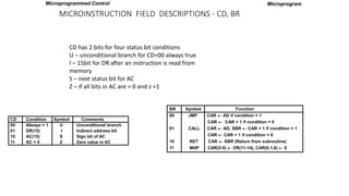
- 14. MICROINSTRUCTION FIELD DESCRIPTIONS - CD, BR CD Condition Symbol Comments 00 Always = 1 U Unconditional branch 01 DR(15) I Indirect address bit 10 AC(15) S Sign bit of AC 11 AC = 0 Z Zero value in AC BR Symbol Function 00 JMP CAR ’é¼ AD if condition = 1 CAR ’é¼ CAR + 1 if condition = 0 01 CALL CAR ’é¼ AD, SBR ’é¼ CAR + 1 if condition = 1 CAR ’é¼ CAR + 1 if condition = 0 10 RET CAR ’é¼ SBR (Return from subroutine) 11 MAP CAR(2-5) ’é¼ DR(11-14), CAR(0,1,6) ’é¼ 0 Microprogram Microprogrammed Control CD has 2 bits for four status bit conditions U ŌĆō unconditional branch for CD=00 always true I ŌĆō 15bit for DR after an instruction is read from memory S ŌĆō next status bit for AC Z ŌĆō if all bits in AC are = 0 and z =1
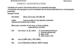
- 15. SYMBOLIC MICROINSTRUCTIONS ŌĆó Symbols are used in microinstructions as in assembly language ŌĆó A symbolic microprogram can be translated into its binary equivalent by a microprogram assembler. Sample Format five fields: label; micro-ops; CD; BR; AD Label: may be empty or may specify a symbolic address terminated with a colon Micro-ops: consists of one, two, or three symbols separated by commas CD: one of {U, I, S, Z}, where U: Unconditional Branch I: Indirect address bit S: Sign of AC Z: Zero value in AC BR: one of {JMP, CALL, RET, MAP} AD: one of {Symbolic address, NEXT, empty} Microprogram Microprogrammed Control
- 16. SYMBOLIC MICROPROGRAM - FETCH ROUTINE AR ’é¼ PC DR ’é¼ M[AR], PC ’é¼ PC + 1 AR ’é¼ DR(0-10), CAR(2-5) ’é¼ DR(11-14), CAR(0,1,6) ’é¼ 0 Symbolic microprogram for the fetch cycle: ORG 64 PCTAR U JMP NEXT READ, INCPC U JMP NEXT DRTAR U MAP FETCH: Binary equivalents translated by an assembler 1000000 110 000 000 00 00 1000001 1000001 000 100 101 00 00 1000010 1000010 101 000 000 00 11 0000000 Binary address F1 F2 F3 CD BR AD Microprogram During FETCH, Read an instruction from memory and decode the instruction and update PC Sequence of microoperations in the fetch cycle: Microprogrammed Control
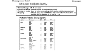
- 17. SYMBOLIC MICROPROGRAM ŌĆó Control Storage: 128 20-bit words ŌĆó The first 64 words: Routines for the 16 machine instructions ŌĆó The last 64 words: Used for other purpose (e.g., fetch routine and other subroutines) ŌĆó Mapping: OP-code XXXX into 0XXXX00, the first address for the 16 routines are 0(0 0000 00), 4(0 0001 00), 8, 12, 16, 20, ..., 60 Microprogram ORG 0 NOP READ ADD ORG 4 NOP NOP NOP ARTPC ORG 8 NOP ACTDR WRITE ORG 12 NOP READ ACTDR, DRTAC WRITE ORG 64 PCTAR READ, INCPC DRTAR READ DRTAR I U U S U I U I U U I U U U U U U U U CALL JMP JMP JMP JMP CALL JMP CALL JMP JMP CALL JMP JMP JMP JMP JMP MAP JMP RET INDRCT NEXT FETCH OVER FETCH INDRCT FETCH INDRCT NEXT FETCH INDRCT NEXT NEXT FETCH NEXT NEXT NEXT ADD: BRANCH: OVER: STORE: EXCHANGE: FETCH: INDRCT: Label Microops CD BR AD Partial Symbolic Microprogram Microprogrammed Control
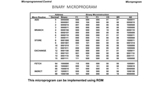
- 18. This microprogram can be implemented using ROM Microprogram Address Binary Microinstruction Micro Routine Decimal Binary F1 F2 F3 CD BR AD ADD 0 0000000 000 000 000 01 01 1000011 1 0000001 000 100 000 00 00 0000010 2 0000010 001 000 000 00 00 1000000 3 0000011 000 000 000 00 00 1000000 BRANCH 4 0000100 000 000 000 10 00 0000110 5 0000101 000 000 000 00 00 1000000 6 0000110 000 000 000 01 01 1000011 7 0000111 000 000 110 00 00 1000000 STORE 8 0001000 000 000 000 01 01 1000011 9 0001001 000 101 000 00 00 0001010 10 0001010 111 000 000 00 00 1000000 11 0001011 000 000 000 00 00 1000000 EXCHANGE 12 0001100 000 000 000 01 01 1000011 13 0001101 001 000 000 00 00 0001110 14 0001110 100 101 000 00 00 0001111 15 0001111 111 000 000 00 00 1000000 FETCH 64 1000000 110 000 000 00 00 1000001 65 1000001 000 100 101 00 00 1000010 66 1000010 101 000 000 00 11 0000000 INDRCT 67 1000011 000 100 000 00 00 1000100 68 1000100 101 000 000 00 10 0000000 BINARY MICROPROGRAM Microprogrammed Control
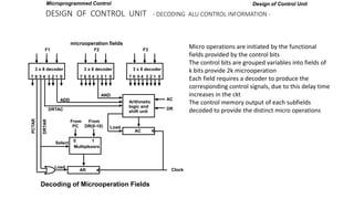
- 19. DESIGN OF CONTROL UNIT - DECODING ALU CONTROL INFORMATION - Design of Control Unit microoperation fields 3 x 8 decoder 7 6 5 4 3 2 1 0 F1 3 x 8 decoder 7 6 5 4 3 2 1 0 F2 3 x 8 decoder 7 6 5 4 3 2 1 0 F3 Arithmetic logic and shift unit AND ADD DRTAC AC Load From PC From DR(0-10) Select 0 1 Multiplexers AR Load Clock AC DR DRTAR PCTAR Decoding of Microoperation Fields Microprogrammed Control Micro operations are initiated by the functional fields provided by the control bits The control bits are grouped variables into fields of k bits provide 2k microoperation Each field requires a decoder to produce the corresponding control signals, due to this delay time increases in the ckt The control memory output of each subfields decoded to provide the distinct micro operations
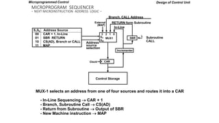
- 20. MICROPROGRAM SEQUENCER - NEXT MICROINSTRUCTION ADDRESS LOGIC - Design of Control Unit Subroutine CALL MUX-1 selects an address from one of four sources and routes it into a CAR - In-Line Sequencing ’é« CAR + 1 - Branch, Subroutine Call ’é« CS(AD) - Return from Subroutine ’é« Output of SBR - New Machine instruction ’é« MAP 3 2 1 0 S S 1 0 MUX1 External (MAP) SBR L Incrementer CAR Clock Address source selection In-Line RETURN form Subroutine Branch, CALL Address Control Storage S1S0 Address Source 00 CAR + 1, In-Line 01 SBR RETURN 10 CS(AD), Branch or CALL 11 MAP Microprogrammed Control
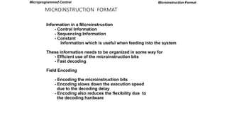
- 21. MICROINSTRUCTION FORMAT Microinstruction Format Information in a Microinstruction - Control Information - Sequencing Information - Constant Information which is useful when feeding into the system These information needs to be organized in some way for - Efficient use of the microinstruction bits - Fast decoding Field Encoding - Encoding the microinstruction bits - Encoding slows down the execution speed due to the decoding delay - Encoding also reduces the flexibility due to the decoding hardware Microprogrammed Control
- 22. HORIZONTAL AND VERTICAL MICROINSTRUCTION FORMAT Horizontal Microinstructions Each bit directly controls each micro-operation or each control point Horizontal implies a long microinstruction word Advantages: Can control a variety of components operating in parallel. --> Advantage of efficient hardware utilization Disadvantages: Control word bits are not fully utilized --> CS becomes large --> Costly Vertical Microinstructions A microinstruction format that is not horizontal Vertical implies a short microinstruction word Encoded Microinstruction fields --> Needs decoding circuits for one or two levels of decoding Microinstruction Format One-level decoding Field A 2 bits 2 x 4 Decoder 3 x 8 Decoder Field B 3 bits 1 of 4 1 of 8 Two-level decoding Field A 2 bits 2 x 4 Decoder 6 x 64 Decoder Field B 6 bits Decoder and selection logic Microprogrammed Control
- 23. NANOSTORAGE AND NANOINSTRUCTION The decoder circuits in a vertical microprogram storage organization can be replaced by a ROM => Two levels of control storage First level - Control Storage Second level - Nano Storage Two-level microprogram First level -Vertical format Microprogram Second level -Horizontal format Nanoprogram - Interprets the microinstruction fields, thus converts a vertical microinstruction format into a horizontal nanoinstruction format. Usually, the microprogram consists of a large number of short microinstructions, while the nanoprogram contains fewer words with longer nanoinstructions. Control Storage Hierarchy Microprogrammed Control
- 24. TWO-LEVEL MICROPROGRAMMING - EXAMPLE * Microprogram: 2048 microinstructions of 200 bits each * With 1-Level Control Storage: 2048 x 200 = 409,600 bits * Assumption: 256 distinct microinstructions among 2048 * With 2-Level Control Storage: Nano Storage: 256 x 200 bits to store 256 distinct nanoinstructions Control storage: 2048 x 8 bits To address 256 nano storage locations 8 bits are needed * Total 1-Level control storage: 409,600 bits Total 2-Level control storage: 67,584 bits (256 x 200 + 2048 x 8) Control Storage Hierarchy Control address register 11 bits Control memory 2048 x 8 Microinstruction (8 bits) Nanomemory address Nanomemory 256 x 200 Nanoinstructions (200 bits) Microprogrammed Control
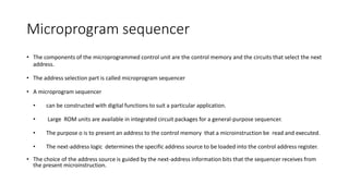
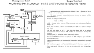
- 25. Microprogram sequencer ŌĆó The components of the microprogrammed control unit are the control memory and the circuits that select the next address. ŌĆó The address selection part is called microprogram sequencer ŌĆó A microprogram sequencer ŌĆó can be constructed with digital functions to suit a particular application. ŌĆó Large ROM units are available in integrated circuit packages for a general-purpose sequencer. ŌĆó The purpose o is to present an address to the control memory that a microinstruction be read and executed. ŌĆó The next-address logic determines the specific address source to be loaded into the control address register. ŌĆó The choice of the address source is guided by the next-address information bits that the sequencer receives from the present microinstruction.
- 26. MICROPROGRAM SEQUENCER- internal structure with one subroutine register Design of Control Unit 3 2 1 0 S1 MUX1 External (MAP) SBR Load Incrementer CAR Input logic I 0 T MUX2 Select 1 I S Z Test Clock Control memory Microops CD BR AD L I 1 S0 . . . . . . Microprogrammed Control the internal structure of a microprogram sequencer to show a particular unit that is suitable for use in the microprogram The control memory is to show the interaction between the sequencer and the memory attached to it. There are two multiplexers in the circuit. MUX1 and MUX2 MUX1 - selects an address from one of four sources and routes it into a control address register CAR. MUX2 - tests the value of a selected status bit and the result of the test is applied to an input logic circuit. The other three inputs to MUX1 come from the address field of the present microinstruction, from the output of SBR, and from an external source that maps the instruction. The output from CAR provides the address for the control memory. The content of CAR is incremented and applied to one of the multiplexer inputs and to the subroutine register SBR. The CD (condition) field of the microinstruction selects one of the status bits in the second multiplexer If the bit selected is equal to 1, the T (test) variable is equal to 1; otherwise, it is equal to 0. The T value together with the two bits from the BR (branch) field go to an input logic circuit.
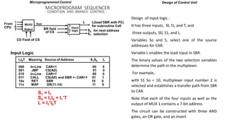
- 27. MICROPROGRAM SEQUENCER - CONDITION AND BRANCH CONTROL - Design of Control Unit Input logic I0 I 1 T MUX2 Select 1 I S Z Test CD Field of CS From CPU BR field of CS L(load SBR with PC) for subroutine Call S0 S1 for next address selection I1I0T Meaning Source of Address S1S0 L 000 In-Line CAR+1 00 0 001 JMP CS(AD) 01 0 010 In-Line CAR+1 00 0 011 CALL CS(AD) and SBR <- CAR+1 01 1 10x RET SBR 10 0 11x MAP DR(11-14) 11 0 L S1 = I1 S0 = I1I0 + I1ŌĆÖT L = I1ŌĆÖI0T Input Logic Microprogrammed Control Design of input logic : It has three inputs, l0, l1, and T, and three outputs, S0, S1, and L. Variables So and S, select one of the source addresses for CAR. Variable L enables the load input in SBR. The binary values of the two selection variables determine the path in the multiplexer. For example, with S1 So = 10, multiplexer input number 2 is selected and establishes a transfer path from SBR to CAR. Note that each of the four inputs as well as the output of MUX 1 contains a 7-bit address The circuit can be constructed with three AND gates, an OR gate, and an invert