The document discusses failure mode and effects analysis (FMEA). It provides definitions and descriptions of different types of FMEAs, including design FMEA (DFMEA) which focuses on potential design failures, and process FMEA (PFMEA) which focuses on potential process failures and their causes. The document outlines the key steps in conducting a PFMEA, including developing a process flow diagram, identifying potential failure modes and their effects and causes, analyzing the risks associated with failures, and creating a process control plan to address potential failures.
CADmantra Technologies Pvt. Ltd. is one of the best Cad training company in northern zone in India . which are provided many types of courses in cad field i.e AUTOCAD,SOLIDWORK,CATIA,CRE-O,Uniraphics-NX, CNC, REVIT, STAAD.Pro. And many courses
Contact: www.cadmantra.com
www.cadmantra.blogspot.com
www.cadmantra.wix.com
FMEA is a failure mode and effects analysis that helps engineers anticipate failures and prevent them. It involves identifying potential failure modes, their causes and effects. It calculates a risk priority number based on the severity, occurrence, and detection of each failure. This helps prioritize actions to address high risk failures through improved design or detection controls. The goal is to understand the design well enough to anticipate and prevent failures.
This document provides an overview of failure mode and effects analysis (FMEA). It defines FMEA as a method to identify potential failure modes, causes, and effects. The document outlines the history of FMEA, from its origins in 1955 to its widespread use today. It also describes the different types of FMEA (system, design, process) and when each is applied. Key aspects of performing a process FMEA like potential causes, controls, severity, occurrence, detection, and risk priority number are defined.
FMEA is a procedure for analyzing potential failures in a system. It helps identify failures, classify them by severity, and determine how failures affect the system. FMEA is used in manufacturing to design quality and reliability into products early in development. It involves identifying potential failure modes, studying their effects, and recommending actions to address failures with high risks. FMEA aims to improve reliability by analyzing failures before problems occur.
This document provides an overview of failure mode and effects analysis (FMEA). FMEA is a systematic process for identifying potential failures in a design, manufacturing or production process. It involves reviewing all possible failures, their causes and effects. Potential failures are then ranked according to severity, occurrence, and detection. This allows teams to prioritize high risk failures and identify actions to address them. The document outlines the basic FMEA process including defining potential failures and their effects, identifying causes, current controls and assigning ratings. It also describes how to calculate a risk priority number and use FMEAs to drive process improvement.
This document provides an overview of failure mode and effects analysis (FMEA). FMEA is a systematic process for identifying potential failures in a design, manufacturing or production process. It involves reviewing all possible failures, their causes and effects. Potential failures are ranked according to severity, occurrence, and the ability to detect the failure. This ranking is used to identify areas that need improvement and prevent potential problems. The document discusses the different types of FMEAs (e.g. design, process), how to conduct one including using a worksheet to document the analysis, and how FMEAs can benefit processes by reducing risks and costs.
The document discusses Failure Modes and Effects Analysis (FMEA), which is a systematic method used to evaluate processes and identify potential failures, causes, and effects. It also assesses the impact of different failures to identify parts of the process most in need of improvement. FMEA involves reviewing process steps, potential failure modes and causes, failure effects, and uses a team approach. It aims to evaluate processes proactively for failures and prevent them by correcting processes before failures occur. FMEA is useful for new processes prior to implementation and assessing changes to existing processes. It provides a structured way to identify risks in processes.
Previously presented at the Plex Supply Chain Community Conference on February 25, 2015. Improving the Plex Manufacturing Cloud in Honda Supply Chain environment
A complete guide on preparation, planning and execution of a computerized maintenance management system with examples and illustration of the program modules interaction and the way these programs operate.
The document outlines the control phase tools and activities for a Lean Six Sigma project. It includes reviewing project documentation, validating goals and benefits, developing standard operating procedures and controls, implementing and monitoring the solution, confirming attainment of goals, identifying opportunities for replication, and transitioning the project to the process owner. Key metrics are monitored to ensure the process remains in control. Lessons learned are captured to improve future projects.
The document outlines the control phase tools and activities in a Lean Six Sigma project. It includes reviewing project documentation and metrics, developing standard operating procedures and controls, implementing and monitoring the solution, confirming goals are met, identifying opportunities for replication, and transitioning the project to the process owner. Key steps are developing a control plan to monitor processes and respond to variation, updating failure modes and effects analysis, and communicating project results and benefits.
FMEA - What is FMEA. Everything about FMEA.Dheeraj Chavan
Ìý
FMEA is a structured approach to recognize and evaluate potential failures and their effects. It identifies actions to eliminate or reduce failures and documents the process. FMEA involves assessing the severity, occurrence, and detection of potential failures to determine a risk priority number. Higher risk failures are prioritized for corrective actions like design changes or verifications. FMEA is conducted by a team and is an ongoing process throughout the product lifecycle to prevent known and potential problems.
This document discusses advances in fault detection and diagnosis in industry. It covers condition monitoring techniques like vibration analysis, lubricant analysis, and thermography. It discusses the differences between fault, failure, and malfunction and describes fault detection as detecting small faults early through techniques like limit checking and trend analysis. Fault diagnosis involves diagnosing faults in processes, parts, and devices using analytical and heuristic methods. Condition monitoring systems are discussed along with fault detection models using process variables. Data analysis techniques and online enterprise asset management are also covered.
FMEA is a systematic method to identify potential failures, quantify risks, and determine actions to address issues. It involves analyzing potential failure modes and their causes and effects. Failures are evaluated based on severity, occurrence likelihood, and detection difficulty to calculate a risk priority number. Actions are identified and prioritized based on RPN to prevent or mitigate risks. FMEA is used across industries to improve safety, quality and reliability.
PFMEA, Risk Reduction and Effectiveness – Advance (AIAG FMEA #4 Edition)
Is your FMEA performing for you?
This is advance level of PFMEA, Have basic understanding fo Core IATF Tools before refering to this presentation.
Here are the key steps to conduct a variable MSA:
1. Select a part/product with known measurements.
2. Select operators who will use the measurement system.
3. Have operators measure the part multiple times.
4. Analyze the data using one of the methods:
- Bias study to determine if the measurement system is accurate.
- Linearity study to determine if measurements are proportional to actual size.
- Stability study to determine if measurements drift over time.
- Repeatability & reproducibility study to determine precision between and within operators.
5. Compare results to customer specifications for capability. Ensure Cp, Cpk are greater than 1.33.
Control-Plan-Training.pptx for the Automotive standard AIAGVikrantPawar37
Ìý
This document provides training on control plans, which are used to systematically control processes. It discusses key aspects of control plans such as identifying product and process characteristics, establishing specifications and control methods, and defining reaction plans. The objectives are to understand how to develop a control plan and link each step to the process FMEA. A plug assembly control plan example is also provided to demonstrate how to structure the control plan.
This document provides an overview of process failure mode and effects analysis (PFMEA). It discusses the steps to conduct a PFMEA, including identifying critical process steps and their potential failure modes, effects, causes, controls, and risk priority numbers. The goals of a PFMEA are to proactively identify potential process failures, prioritize issues based on risk, and determine actions to reduce failures and improve process quality, reliability, and customer satisfaction. Conducting a thorough PFMEA requires a cross-functional team approach.
Failure Modes and Effects Analysis (FMEA) is a systematic tool used to identify potential failures, their causes, and effects. It helps prioritize issues based on a Risk Priority Number calculated from severity, occurrence, and detection ratings. FMEA was first used in the aerospace industry and has since been applied to automotive and other sectors. The analysis involves identifying failure modes, causes, and effects, then taking actions to reduce risks.
This document provides guidance on conducting a Design Failure Mode and Effects Analysis (DFMEA). It begins with defining the purpose of a FMEA and what it involves. It then discusses current DFMEA practices and concerns. The remainder of the document offers detailed instructions on performing a DFMEA, including how to construct a process flow diagram, interface matrix, evaluate potential failure modes and their effects/severity, occurrence, detection, and risk priority numbers. It provides examples and criteria for properly analyzing risk and prioritizing corrective actions. The overall summary is that the document aims to refine the approach to DFMEAs by outlining the full process and key considerations for effectively conducting a thorough design risk assessment.
This document provides an overview of conducting a Process Failure Modes and Effects Analysis (P-FMEA). A P-FMEA helps improve processes, reduce failures, monitor production issues, improve quality checks, and teaches systematic analysis. The key steps include: 1) Listing all process steps and potential failures, 2) Estimating the likelihood of failures, 3) Recording prevention and detection actions, 4) Calculating a Risk Priority Number, and 5) Proposing improvements for high priority risks. An example of analyzing a solar concentrator subsystem in a solar power system is provided. The assumptions, inputs/outputs, and 6-step approach to conducting a P-FMEA are outlined.
The document summarizes a study on performing a Process Failure Mode and Effect Analysis (FMEA) on an end milling process. The researchers conducted multiple end milling trials and identified several potential failure modes and their effects. They assigned severity, occurrence, and detection ratings to each failure mode and calculated Risk Priority Numbers. The failure mode with the highest RPN, which was chip packing, was further analyzed to identify causes and recommend preventive measures like adjusting feed or speed. The FMEA provides a guide to prevent failures and improve the effectiveness of end milling operations.
This PPT covers the index and engineering properties of soil. It includes details on index properties, along with their methods of determination. Various important terms related to soil behavior are explained in detail. The presentation also outlines the experimental procedures for determining soil properties such as water content, specific gravity, plastic limit, and liquid limit, along with the necessary calculations and graph plotting. Additionally, it provides insights to understand the importance of these properties in geotechnical engineering applications.
Optimization of Cumulative Energy, Exergy Consumption and Environmental Life ...J. Agricultural Machinery
Ìý
Optimal use of resources, including energy, is one of the most important principles in modern and sustainable agricultural systems. Exergy analysis and life cycle assessment were used to study the efficient use of inputs, energy consumption reduction, and various environmental effects in the corn production system in Lorestan province, Iran. The required data were collected from farmers in Lorestan province using random sampling. The Cobb-Douglas equation and data envelopment analysis were utilized for modeling and optimizing cumulative energy and exergy consumption (CEnC and CExC) and devising strategies to mitigate the environmental impacts of corn production. The Cobb-Douglas equation results revealed that electricity, diesel fuel, and N-fertilizer were the major contributors to CExC in the corn production system. According to the Data Envelopment Analysis (DEA) results, the average efficiency of all farms in terms of CExC was 94.7% in the CCR model and 97.8% in the BCC model. Furthermore, the results indicated that there was excessive consumption of inputs, particularly potassium and phosphate fertilizers. By adopting more suitable methods based on DEA of efficient farmers, it was possible to save 6.47, 10.42, 7.40, 13.32, 31.29, 3.25, and 6.78% in the exergy consumption of diesel fuel, electricity, machinery, chemical fertilizers, biocides, seeds, and irrigation, respectively.
Air pollution is contamination of the indoor or outdoor environment by any ch...dhanashree78
Ìý
Air pollution is contamination of the indoor or outdoor environment by any chemical, physical or biological agent that modifies the natural characteristics of the atmosphere.
Household combustion devices, motor vehicles, industrial facilities and forest fires are common sources of air pollution. Pollutants of major public health concern include particulate matter, carbon monoxide, ozone, nitrogen dioxide and sulfur dioxide. Outdoor and indoor air pollution cause respiratory and other diseases and are important sources of morbidity and mortality.
WHO data show that almost all of the global population (99%) breathe air that exceeds WHO guideline limits and contains high levels of pollutants, with low- and middle-income countries suffering from the highest exposures.
Air quality is closely linked to the earth’s climate and ecosystems globally. Many of the drivers of air pollution (i.e. combustion of fossil fuels) are also sources of greenhouse gas emissions. Policies to reduce air pollution, therefore, offer a win-win strategy for both climate and health, lowering the burden of disease attributable to air pollution, as well as contributing to the near- and long-term mitigation of climate change.
Preface: The ReGenX Generator innovation operates with a US Patented Frequency Dependent Load Current Delay which delays the creation and storage of created Electromagnetic Field Energy around the exterior of the generator coil. The result is the created and Time Delayed Electromagnetic Field Energy performs any magnitude of Positive Electro-Mechanical Work at infinite efficiency on the generator's Rotating Magnetic Field, increasing its Kinetic Energy and increasing the Kinetic Energy of an EV or ICE Vehicle to any magnitude without requiring any Externally Supplied Input Energy. In Electricity Generation applications the ReGenX Generator innovation now allows all electricity to be generated at infinite efficiency requiring zero Input Energy, zero Input Energy Cost, while producing zero Greenhouse Gas Emissions, zero Air Pollution and zero Nuclear Waste during the Electricity Generation Phase. In Electric Motor operation the ReGen-X Quantum Motor now allows any magnitude of Work to be performed with zero Electric Input Energy.
Demonstration Protocol: The demonstration protocol involves three prototypes;
1. Protytpe #1, demonstrates the ReGenX Generator's Load Current Time Delay when compared to the instantaneous Load Current Sine Wave for a Conventional Generator Coil.
2. In the Conventional Faraday Generator operation the created Electromagnetic Field Energy performs Negative Work at infinite efficiency and it reduces the Kinetic Energy of the system.
3. The Magnitude of the Negative Work / System Kinetic Energy Reduction (in Joules) is equal to the Magnitude of the created Electromagnetic Field Energy (also in Joules).
4. When the Conventional Faraday Generator is placed On-Load, Negative Work is performed and the speed of the system decreases according to Lenz's Law of Induction.
5. In order to maintain the System Speed and the Electric Power magnitude to the Loads, additional Input Power must be supplied to the Prime Mover and additional Mechanical Input Power must be supplied to the Generator's Drive Shaft.
6. For example, if 100 Watts of Electric Power is delivered to the Load by the Faraday Generator, an additional >100 Watts of Mechanical Input Power must be supplied to the Generator's Drive Shaft by the Prime Mover.
7. If 1 MW of Electric Power is delivered to the Load by the Faraday Generator, an additional >1 MW Watts of Mechanical Input Power must be supplied to the Generator's Drive Shaft by the Prime Mover.
8. Generally speaking the ratio is 2 Watts of Mechanical Input Power to every 1 Watt of Electric Output Power generated.
9. The increase in Drive Shaft Mechanical Input Power is provided by the Prime Mover and the Input Energy Source which powers the Prime Mover.
10. In the Heins ReGenX Generator operation the created and Time Delayed Electromagnetic Field Energy performs Positive Work at infinite efficiency and it increases the Kinetic Energy of the system.
Preface: The ReGenX Generator innovation operates with a US Patented Frequency Dependent Load
Current Delay which delays the creation and storage of created Electromagnetic Field Energy around
the exterior of the generator coil. The result is the created and Time Delayed Electromagnetic Field
Energy performs any magnitude of Positive Electro-Mechanical Work at infinite efficiency on the
generator's Rotating Magnetic Field, increasing its Kinetic Energy and increasing the Kinetic Energy of
an EV or ICE Vehicle to any magnitude without requiring any Externally Supplied Input Energy. In
Electricity Generation applications the ReGenX Generator innovation now allows all electricity to be
generated at infinite efficiency requiring zero Input Energy, zero Input Energy Cost, while producing
zero Greenhouse Gas Emissions, zero Air Pollution and zero Nuclear Waste during the Electricity
Generation Phase. In Electric Motor operation the ReGen-X Quantum Motor now allows any
magnitude of Work to be performed with zero Electric Input Energy.
Demonstration Protocol: The demonstration protocol involves three prototypes;
1. Protytpe #1, demonstrates the ReGenX Generator's Load Current Time Delay when compared
to the instantaneous Load Current Sine Wave for a Conventional Generator Coil.
2. In the Conventional Faraday Generator operation the created Electromagnetic Field Energy
performs Negative Work at infinite efficiency and it reduces the Kinetic Energy of the system.
3. The Magnitude of the Negative Work / System Kinetic Energy Reduction (in Joules) is equal to
the Magnitude of the created Electromagnetic Field Energy (also in Joules).
4. When the Conventional Faraday Generator is placed On-Load, Negative Work is performed and
the speed of the system decreases according to Lenz's Law of Induction.
5. In order to maintain the System Speed and the Electric Power magnitude to the Loads,
additional Input Power must be supplied to the Prime Mover and additional Mechanical Input
Power must be supplied to the Generator's Drive Shaft.
6. For example, if 100 Watts of Electric Power is delivered to the Load by the Faraday Generator,
an additional >100 Watts of Mechanical Input Power must be supplied to the Generator's Drive
Shaft by the Prime Mover.
7. If 1 MW of Electric Power is delivered to the Load by the Faraday Generator, an additional >1
MW Watts of Mechanical Input Power must be supplied to the Generator's Drive Shaft by the
Prime Mover.
8. Generally speaking the ratio is 2 Watts of Mechanical Input Power to every 1 Watt of Electric
Output Power generated.
9. The increase in Drive Shaft Mechanical Input Power is provided by the Prime Mover and the
Input Energy Source which powers the Prime Mover.
10. In the Heins ReGenX Generator operation the created and Time Delayed Electromagnetic Field
Energy performs Positive Work at infinite efficiency and it increases the Kinetic Energy of the
system.
3. Training Program on Process Flow Diagram
WHY?
To understand all the processes involved from the
Incoming stage to the final product despatch.
BENIFITS
 Can able to see at once all the processes
 Allows each operation to questioned
 Exposes source variations
 Highlights Non Value Added activities involved in the process
ºÝºÝߣ 01 of 09
4. Training Program on Process Flow Diagram
ºÝºÝߣ 01A of 09
Understand the Process
Critical Failure Points
Where to Control
Exercise the Control
Good Product
Process Flow
FMEA
Control Plan
Work
Instruction
5. Training Program on Process Flow Diagram
INPUTS OF PFD
(Process Flow Diagram)
 Customer Drawings
 In-process Drawings
 Plant Layout
 Design FMEA outputs
 FMEA for Similar Products
ºÝºÝߣ 02 of 09
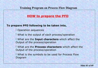
6. Training Program on Process Flow Diagram
HOW to prepare the PFD
To prepare PFD following to be taken into,
 Operation sequences
 What is the output of each process/operation
 What are the Input characters which affect the
Output of the process/operation
 What are the Process characters which affect the
Output of the process/operation
 What is the symbols to be used for Process Flow
Diagram
ºÝºÝߣ 03 of 09
7. Training Program on Process Flow Diagram
Oper.no
Operation
Description
Incomming
Source
Variation
PFD
Product
Characteristics /
Desired Outcome
Process
Characteristics
1 2 4 6 3 5
As per the above sequence only Process Flow should be filled
ºÝºÝߣ 04 of 09
8. Training Program on Process Flow Diagram
OPERATION No. & DESCRIPTION
Following guide line shall be followed to provide the Operation nos
for the processes.
Category Operation Nos.
1 One Machine -One operation OP 10, OP 20, OP 30...
2
One Machine-Multi Operations In this
Component cannot be checked stage wise by
manually or automatically till the operation
completed.
OP 10, OP 20, OP 30...
3
One Machine-Multi Operations In this
Cccomponent can be checked stage wise by
manually or automatically.
OP 10, OP 10A, OP 10B,
OP 10C,..., OP 20, OP30,...
ºÝºÝߣ 05 of 09
9. Training Program on Process Flow Diagram
Incoming Source Variations (ISV)
This could be due to
 Raw Material
If it is due to Raw Material variation Check the
Supplier FMEA,Process Flow, etc.
 Any Previous Operation’s out comes
If it is due to any Previous operations, clearly specify
the operation/machine from where this Variation occurred.
Also note that these ISVs are not the outcome of this
particular operation
ºÝºÝߣ 06 of 09
10. Training Program on Process Flow Diagram
Product Characteristics/Desired Outcome
These are the characters which to be obtained from the
particular operation.
This Desired outcome shall be one or more of the below
mentioned.
 Blue Print (BP)
 Engineering Specifications (ES)
 In process Characteristics (IP)
 Functional Characteristics (FC)
 Regulatory
ºÝºÝߣ 07 of 09
11. Training Program on Process Flow Diagram
Process Characteristics
 These are also the Characters which affects the Desired
Outcome during the particular operation.
 These can be from one or more of the below mentioned
 Men
 Machine
 Method
 Process Materials
 Environment
ºÝºÝߣ 08 of 09
12. Training Program on Process Flow Diagram
Process Flow Diagram
 Process Flow Diagram identifies
 Where the inspection is carried out
 Where the Operator involvement is required
 Where the Delay is occurred during the process
This process flow Diagram (with the symbols)
indicates, where ever the Non Value Added
actives are there in the process
ºÝºÝߣ 09 of 09
14. WHY FMEA
Tool for 6 SIGMA
Catch the cause before the problem occurs
Prevent the failure
Easy understanding of Process
Reducing the cost of poor quality
Customer Satification
Optimize the controls
15. PROCESS FMEA
1 EFFECT ANALYSIS
2 CAUSAL ANALYSIS
3 CONTROL ANALYSIS
opposite negative
desired isv,process
outcome char.
OPN OPERATION/ POTENTIAL POTENTIAL SEV CLASS POTENTIAL OCCUR CURRENT PROCESS CURRENT PROCESSDECT. RPN
NO. DESCRIPTION FAILURE EFFECT NO CAUSE NO CONTROL PREV. CONTROL DETECT. NO
MODE
next process
assy
customer
field feed
speed
skill
Tool wear
16. Special Characteristics
Critical Characteristics Severity number 10 & 9
Significant Characteristics Severity number is 8& 7
Potential Failure Mode
It is opposite of the desired outcome in the PFD
Potential Effects
what are the effects of the failure at
1 Next Process
2 Assembly
3 Customer
4 Field
EFFECT ANALYSIS
17. Potential cause
negative of incoming source of variation and process Characteristics
3 M's & 1 E
men,material,machines,Environment
GUIDELINES FOR OCCURRENCE NUMBER
1 Occurrence number is to be calculated for causes based upon
actual data
2 If data is not there related to cause,calculate the occurrence no.
of the failure mode data and same occurance number has to be
transferred to the causes using engineering judgement
3 If you don't have data related failure mode & causes,calculate
occurrence number based on the Cpk Value
4 If the above 3 is not available,use the occurrence number from
similar product
5 None of these are available,use the "GUT FEEL"
18. 1 "A" TYPE OF CONTROL- It is detection of failure mode(Inspection)
2 "B" TYPE OF CONTROL- It is detection of cause
3 "C" TYPE OF CONTROL-Prevention of cause.
"A" Type- Control Plan,Patrol Inspection,Layout Inspection
"B" Type - if the tool is inspected and run
"C" Type-Work Instruction,Service Training
CONTROL
19. 1 RPN Calculation is to be done for failure mode as well as the cause
2 For calculating RPN for failure mode,we have to multiple max.severity
number,occurrence number of the failure mode and "A" Type
control detection number
3 For calculating RPN for failure mode,we have to multiple max.severity
number,occurrence number that specified cause & min of detection
number of "A" type control & "B" type control of that cause
RPN
At what Risk the customer is operating the job?
RPN for failure mode -for customer's
RPN for Causes-for the manufactures
RPN can be high (if the detection number is high)
RPN CALCULATION
20. 1 Make a pareto of RPN of failure mode and identify which
failure mode is contributing 80%
2 After that,pareto of causes RPN which is contributing above
80% of failure mode to be done.
3 When ever that occurrence number of cause is greater than 3,
we have to take recommended action.
4 Whenever the severity number is 7,8,9,10,we have to introduce
"A" type of control.
GUIDELINES FOR RECOMMENDED ACTION
22. What Is Control Plan
• Is a written summary of the system for controlling the
variation of all product and process characteristics,
important quality and engineering requirements
• Is a contract between the supplier and the customer
• Is used as the basis for development of process work
instruction
• Identifies all customer and supplier specified special
characteristics.
23. CONTROL PLAN
Prototype prelanch production
Control plan number TALOP 001
Latest change level - 01
Description : OP 475 ASSY
Supplier / Plant
PLANT -III
Supplier code
Key contact / Phone
Mr.M.CHIDAMBARANATHAN
26272676
Core team
TAL CFT
Supplier / Part approval / Date
Other approval / Date (If required)
Date (Original)
15.06.03
Date (Revised) Page 1 of 3
Customer engineering approval date (If required)
Customer quality approval date (If required)
Other approval / Date (If required)
Opn. Operation
description
Tool and/
or technique
Characteristics
No Product Process
Class Method
Product /
Process
Specification /
Tolerance
Evaluation /
Measurement/
Technique
Sample
Size Frequency Responsibility Record
Yes / No
Reaction
Plan
Control
Method
10 Idle shaft
pressing
with body
Assy fixture
No.33
Hy.press
No.1
1 Out of
Square
ness
0.05 CMM 2 Every
setting
Cell leader /
operator
YES First of
inspection
report
Stop the
assy and
findout
the root
cause
A)Out of
Square of
press ram
WRT to
bed
B)Over
size of
fixture
bush ID
C)Sudden
press
load
0.10 Dial stand
with angle
plate
Monthly
Maintenance
Engineer
YES History
card
Inform to
mainten
ance and
bed
scrapping
to be done
20.0 + 0.01 Bore dial As per
history card
Development
Engineer
YES History
card
Bush to be
replaced
Ram should
be moved
gradually
Visual 100% Operator No Work
instruction
On job
training
to be given
One
time
25. 5 Levels of PPAP
Level 1 Warrant Only
Level 2 Warrant, Product Samples, Limited Data
Level 3 Warrant, Product Samples, Complete data
submitted
Level 4 Warrant, Other requirements as defined by
the Customer.(All other PPAP Documents)
Level 5 Warrant, Product samples, Complete Data
reviewed at Supplier End.
26. 1. Design records
2. Any Authorize engg. Change
documents
3. Engineering Approval (If Reqd)
4. DFMEA
5. Process Flow Diagram
6. PFMEA
7. Dimensional Reports
8. Material Test reports &
Performance test reports
9. MSA Study
10. SPC study & Cpk Status
11. Qualified calibration lab and
testing lab details
12. Control Plan
13. PSW
14. Appearance Approval Report
15. Bulk material manufacturing
check list
16. Checking Aids
17. Product Samples
18. Master Sample
19. Any Customer Specific
Requirements
19 Requirement of PPAP