


More Related Content
What's hot (20)
Similar to Presentasi E.M. Terapan (Horn Antenna) (20)


Recently uploaded (20)


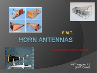
Presentasi E.M. Terapan (Horn Antenna)
- 1. Antena Celah (Aperture Antenna) Alfi Tranggono A.S. (1107 100 015)
- 2. Antena microwave dapat dibagi dalam 6 jenis, yaitu : ’é× 1. Antena Celah (Aperture Antenna) (Sectoral Horn, Piramidal Horn, dll.) ’é× 2. Antena lensa ’é× 3. Antena slot (Antena Susun atau Array) ’é× 4. Antena dielektris (Antena Kabel) (monopole, dipole, loop.) ’é× 5. Antena reflektor (Antena Pantul) (Antena Parabolic dish, corner reflector dll.) ’é× 6. Antena surface wave
- 3. Antena Celah (Aperture Antenna) Antena horn Horn atau elektromagnetik horn alat transisi antara saluran transmisi dan ruang bebas sehingga matching untuk gelombang terbimbing ke gelombang bebas atau sebaliknya. . . . . .horn merupakan waveguide yang diatur sehingga gelombang-gelombang dalam bumbung (celah/horn) menyebar menurut orde tertentu. Dipakai sebagai alat untuk memberikan pengarahan (directivity) gelombang elektromagnet dengan bidang frekuensi
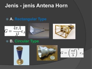
- 4. Jenis - jenis Antena Horn ’é× A. Rectangular Type ’é× B. Circular Type
- 5. Horn Rectangular Type ’é× a. Sectoral Horn, meliputi : ’éŚ - sectoral E-plane ’éŚ E-plane sektoral di arah listrik atau E-lapangan di Waveguide. ’éŚ - sectoral H-plane ’éŚ H-plane sektoral di arah magnetik atau H-field di Waveguide.
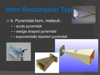
- 6. Horn Rectangular Type ’é× b. Pyramidal horn, meliputi : ’éŚ - acute pyramidal ’éŚ - wedge shaped pyramidal ’éŚ - exponentially tepered pyramidal
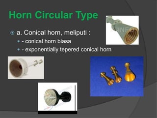
- 7. Horn Circular Type ’é× a. Conical horn, meliputi : ’éŚ - conical horn biasa ’éŚ - exponentially tepered conical horn
- 8. Horn Circular Type ’é× b. Biconical horn : ’éŚ - TEM mode biconical ’éŚ - TG01 mode biconical
- 9. Directivity Horn Dimana : D = Directivity Ae = aperture/celah efektif ( m2 ) Ap = aperture/celah fisik ( m2 ), eap = efisiensi aperture ( Ae / Ap ) ŌĆślamdaŌĆØ = panjang gelombang ( m )