Sequences of pneumatics
Download as DOCX, PDF1 like3,326 views
some sequences of automation operations so that we can automize operation using pneumatics and electropneumatics.
1 of 4
Downloaded 23 times


Recommended
Hydraulic ciruits
Hydraulic ciruitsAbhishek Patange
Ěý
Control of a single-acting and double-acting cylinder, regeneration, motor braking, speed control, synchronisation, fail safe, two handed, application of counterbalance, sequence, unloading, pressure reducing, pilot operated check valve
Introduction to electropneumatic
Introduction to electropneumaticAditya Kurniawan
Ěý
Electropneumatic systems combine pneumatic actuators and controllers with electric control circuits. Pneumatic actuators include cylinders, motors, and valves, which are powered by compressed air. However, the electric control circuits use electrical components like switches, relays, and programmable logic controllers to control the flow of compressed air and automate pneumatic processes. While pneumatic systems can be complicated to control, electropneumatic systems simplify control with digital electric signals regulating complex pneumatic circuits and multiple actuators.Chapter 3 electro pneumatic.updated
Chapter 3 electro pneumatic.updatedHattori Sidek
Ěý
The document discusses electro-pneumatic systems and their components. It describes how electro-pneumatic systems combine electrical and pneumatic components. It provides examples of pneumatic connections and electrical wiring. It also discusses directional control valves, cylinders, basic circuits, and process sequencing methods like narratives, Boolean logic, and diagrams.Introduction to Pneumatic Systems
Introduction to Pneumatic SystemsRAHUL THAKER
Ěý
Introduction to Pneumatic Systems:
Basic Requirements for Pneumatic System,Applications, Pneumatic fundamentals, Construction, working principle and operation of pneumatic power transmission system components like Power source, FRL unit, Actuators and control valves like DCV, FCV, PCV, time delay, quick exhaust, twin pressure, shuttleVelocity Triangle for Moving Blade of an impulse Turbine
Velocity Triangle for Moving Blade of an impulse TurbineShowhanur Rahman
Ěý
Impulse turbines use steam jets to transfer momentum to rotating blades, while reaction turbines use the pressure of steam flowing over stationary and moving blades to rotate the shaft. Both use velocity triangles to analyze steam flow at the inlet and outlet of curved blades. The power produced depends on the change in steam whirl velocity as it flows through the blades. Reaction turbines experience axial thrust from the change in steam flow velocity from inlet to outlet.Basic pneumatic circuit
Basic pneumatic circuitJagabandhu Majumder
Ěý
This document provides an overview of pneumatic control and automation concepts including:
- Standard symbols for pneumatic components like cylinders, valves, and other devices based on ISO 1219 standards.
- Examples of using 2/2 and 3/2 valves to control single-acting cylinders, and 5/2 valves to control double-acting cylinders. Speed control methods like flow regulators are discussed.
- Sequential control concepts and examples of circuits using multiple cylinders operated in sequence are presented.Hydraulic and pneumatic control elements
Hydraulic and pneumatic control elementsumesh chikhale
Ěý
This document discusses various types of hydraulic and pneumatic control elements. It focuses on flow control valves and their purposes.
Flow control valves regulate fluid flow and include pressure control valves, flow control valves, and direction control valves. Pressure control valves such as relief valves and reducing valves maintain system pressure. Flow control valves include compensated and non-compensated types to regulate flow rates. Direction control valves include 2/2, 3/2, and 4/3 styles to control fluid direction to actuators. Proper control elements are necessary to ensure safe and efficient operation of hydraulic and pneumatic systems.Relative Velocity Method for Velocity and Acceleration analysis 
Relative Velocity Method for Velocity and Acceleration analysis Rohit Singla
Ěý
This document discusses methods for analyzing velocity and acceleration in mechanisms. It covers the relative velocity method for analyzing velocity using pole vectors. It also discusses constructing velocity and acceleration diagrams for slider crank mechanisms. The key steps for determining acceleration of a point on a link using an acceleration image are outlined. Components of radial and tangential acceleration are defined. Construction of acceleration diagrams and determining angular acceleration of links is also summarized.Velocity and acceleration of mechanisms
Velocity and acceleration of mechanismsHareesha N Gowda, Dayananda Sagar College of Engg, Bangalore
Ěý
Unit-3 - Velocity and acceleration of mechanisms, Kinematics of machines of VTU Syllabus prepared by Hareesha N Gowda, Asst. Prof, Dayananda Sagar College of Engg, Blore. Please write to hareeshang@gmail.com for suggestions and criticisms. Pressure control valves
Pressure control valvesShrenik Baid
Ěý
This document discusses different types of hydraulic pressure control valves. It describes pressure relief valves, pilot operated relief valves, sequence control valves, and other types. Pressure relief valves limit pressure by diverting fluid to the reservoir when pressure reaches a set point. Pilot operated relief valves use a piston or spool controlled by a pilot valve. Sequence valves provide flow to a second actuator after the first reaches a threshold pressure. The document also provides examples of applications for different valve types.Fluid Mechanics and Turbo Design ch2
Fluid Mechanics and Turbo Design ch2danielmabengo
Ěý
Centrifugal pumps use centrifugal force to raise liquids to higher levels. They work by imparting kinetic energy to the liquid using an impeller. The main parts of a centrifugal pump are the impeller, volute casing, and optional diffuser. The impeller spins and increases the pressure of the liquid flowing through it. The liquid then passes through the volute casing which collects and directs the flow to the outlet pipe. Common pump losses include friction within the impeller and casing as well as leakage losses.Pneumatic circuits
Pneumatic circuitsShukri Ahmaludin
Ěý
The document discusses basic pneumatic circuitry and components for control and automation. It covers pneumatic symbols, circuit layout principles, and examples of actuator control using 2/2, 3/2, and 5/2 valves. The 2/2 valve uses two valves to admit air to move the actuator in one direction and exhaust air to move it in the other. The 3/2 valve provides inlet and exhaust with one valve. The 5/2 valve simultaneously switches the supply and exhaust paths to control a double-acting actuator.compressor notes.pdf
compressor notes.pdfSolotheEngineer
Ěý
The document summarizes key concepts about reciprocating air compressors:
1) It describes the basic components and working of a single-stage, double-acting reciprocating air compressor using a labeled diagram. The compressor consists of a piston that reciprocates in a cylinder driven by a crankshaft, with inlet and outlet valves.
2) It explains the ideal thermodynamic cycle on p-V and T-S diagrams, involving constant-pressure intake, adiabatic compression, and constant-pressure discharge processes.
3) It defines mechanical efficiency and indicated power for reciprocating compressors, and describes calculations for work of compression and various efficiencies like isothermal efficiency.Unit 2.3 Design of Coupling
Unit 2.3 Design of CouplingYugal Kishor Sahu
Ěý
A coupling is a mechanical device that rigidly joins two rotating shafts together. There are three main types of couplings: rigid couplings for perfectly aligned shafts, flexible couplings for shafts with misalignment, and flange couplings which can transmit high torque capacities but do not tolerate misalignment or shocks/vibrations. Design of couplings involves calculating shaft diameters, sleeve/flange dimensions, key dimensions, and bolt diameters based on the transmitted power, material properties, and safety factors. Dimensional relationships and equations are used to check stresses in the various coupling components.Lecture 18 directional valves and symbols
Lecture 18 directional valves and symbolsManipal Institute of Technology
Ěý
The document discusses directional control valves and their components. It describes common types of directional valves like spool valves, poppet valves, and unidirectional valves. It also discusses solenoids and pneumatic and hydraulic systems that use directional control valves to direct fluid flow. Standard symbols for different valve types are presented along with examples of their use in diagrams.Electro hydraulic system Components and their operation
Electro hydraulic system Components and their operationSrichandan Subudhi
Ěý
After this presentation you will be knowing:
1.What are DCVs, its type and their uses
2.About Check Valves and pilot controlled check valves
3.What are solenoid actuated valves and their operation
4.What are proportional solenoid valves and their operation
5.Servo Valve Operation
6.Servo Valve Connector
Nozzle and diffuser
Nozzle and diffuserAvinash Navin
Ěý
This document discusses nozzles and diffusers. It defines nozzles as devices that increase velocity and decrease pressure, and defines diffusers as devices that decrease velocity and increase pressure. Equations for steady flow through nozzles and diffusers using the energy equation are presented. Convergent nozzles are used in most aircrafts while convergent-divergent nozzles are used in supersonic aircraft. The Bernoulli principle is cited to explain how pressure decreases with decreasing area while velocity increases. The conclusion compares flow quality through different nozzle types.Design of hydraulic circuits
Design of hydraulic circuitsHardik Siddhpura
Ěý
This document provides information on various hydraulic circuits used in industrial machinery. It begins with descriptions of basic hydraulic circuits and components. It then discusses more complex industrial circuits for applications like unloading systems to save energy, sequencing cylinders, and regenerative cylinder circuits. It also covers power losses in hydraulic components and methods to reduce losses, such as improving pump efficiency and minimizing pressure drops.Flow control valves
Flow control valvesPranit Mehta
Ěý
In hydraulic and pneumatic systems flow control valves are necessary to vary the speed of actuator. Flow control valves are placed in between Actuator and Direction Control (DC) ValvePresentation on solenoid valve
Presentation on solenoid valveSiya Agarwal
Ěý
A solenoid valve is an electrically controlled valve that uses a solenoid to regulate air movement. It contains a magnetic coil, valve stem, valve sheet, inlet, outlet, plunger and breakaway pin. Solenoid valves are used to control hydraulic systems and mix or distribute air in applications like RO purifiers and dust collectors.Governing of the Turbine | Fluid Mechanics
Governing of the Turbine | Fluid MechanicsSatish Taji
Ěý
Watch Video of this presentation on Link: https://youtu.be/LmJtNo-zgjo
For notes/articles, Visit my blog (link is given below).
For Video, Visit our YouTube Channel (link is given below).
Any Suggestions/doubts/reactions, please leave in the comment box.
Follow Us on
YouTube: https://www.youtube.com/channel/UCVPftVoKZoIxVH_gh09bMkw/
Blog: https://e-gyaankosh.blogspot.com/
Facebook: https://www.facebook.com/egyaankosh/Basic hydraulic circuit
Basic hydraulic circuitCik Aisyahfitrah
Ěý
This document provides an overview of basic hydraulic circuits. It describes how hydraulic systems are divided into a signal control section and a hydraulic power section. The power section includes a pump, valves to control fluid flow and pressure, and hydraulic cylinders or motors. Simple circuits are shown including a pump, directional control valve, cylinder, and pressure relief valve. The interactions of these components in a basic circuit are illustrated through animations. Additional diagrams demonstrate uses of filters, contamination indicators, and pressure relief valves, including how a brake valve is used to prevent pressure spikes when a directional control valve closes suddenly.Gas turbine
Gas turbinenaphis ahamad
Ěý
A gas turbine uses a gaseous working fluid to generate mechanical power that can power industrial devices. It has three main parts - an air compressor, combustion chamber, and turbine. The air is compressed in the compressor, mixed with fuel and ignited in the combustion chamber, and the hot gases spin the turbine to generate power. Some applications of gas turbines include aviation, power generation, and the oil and gas industry. The efficiency of gas turbines is typically 20-30% compared to 38-48% for steam power plants.Static and Dynamic Balancing of Rotating Mass
Static and Dynamic Balancing of Rotating MassAtish kumar Sahoo
Ěý
The document discusses static and dynamic balancing of rotating masses. Static balancing ensures the center of gravity remains stationary during rotation by balancing out centrifugal forces in any radial direction. Dynamic balancing prevents vibration during rotation by statically balancing and also balancing out moments and couples involved in accelerating moving parts. The types of balancing are defined as static, where forces due to gravity are balanced, and dynamic, where inertia forces are balanced in addition to static balance. Benefits include reduced vibration, noise, stresses, and increased quality, bearing life, and efficiency. Balancing is necessary to prevent problems from vibration like noise, abrasion, and shortened machine life.Hydraulic Maintenance and Troubleshooting
Hydraulic Maintenance and TroubleshootingCMA/Flodyne/Hydradyne
Ěý
Troubleshooting hydraulic systems: methods for better understanding and enhanced performance. (CMA/Flodyne/Hydradyne) Drive for Technology 2010Applied Fluid Mechanics - Course Overview (AFD0)
Applied Fluid Mechanics - Course Overview (AFD0)Chemical Engineering Guy
Ěý
This document provides an overview of a course on applied fluid mechanics for incompressible flow. The course is divided into two parts, with part 1 focusing on incompressible flow (60%) and part 2 on compressible flow (40%). Part 1 covers topics like the mechanic energy equation, piping systems, pumps, and applications. It is designed for engineering students and professionals working with moving fluids of constant density. The document outlines the structure, content, textbooks, and importance of understanding incompressible flow for engineering design and operations.Chain drives
Chain drivesMohamed Mohamed El-Sayed
Ěý
The document discusses key concepts related to chain drives, including:
1) It defines common terms used in chain drives like pitch, pitch circle diameter, and velocity ratio.
2) It describes different types of chains including hoisting/hauling chains, conveyor chains, and power transmitting chains like roller chains and silent chains.
3) It provides equations for calculating important chain drive dimensions and specifications like length of chain, center distance, factor of safety, power transmitted, and number of teeth on sprockets.Module 2 instantenous center method
Module 2 instantenous center methodtaruian
Ěý
This document discusses instantaneous centers and their application in mechanisms. It begins by defining an instantaneous center as the point about which pure rotational motion can be assumed for a link undergoing combined translation and rotation. It describes how to locate instantaneous centers based on the bisectors of chords formed by the initial and final positions of links. The document outlines different types of instantaneous centers and provides rules for their location in various joint configurations. It introduces the Aronhold-Kennedy theorem stating that three bodies in relative plane motion will have three instantaneous centers collinear on a straight line. Methods for determining the velocity of points on links and locating all instantaneous centers in a mechanism are presented. An example problem is given to locate
Wireless-Charger presentation for seminar .pdf
Wireless-Charger presentation for seminar .pdfAbhinandanMishra30
Ěý
Wireless technology used in chargerMore Related Content
What's hot (20)
Velocity and acceleration of mechanisms
Velocity and acceleration of mechanismsHareesha N Gowda, Dayananda Sagar College of Engg, Bangalore
Ěý
Unit-3 - Velocity and acceleration of mechanisms, Kinematics of machines of VTU Syllabus prepared by Hareesha N Gowda, Asst. Prof, Dayananda Sagar College of Engg, Blore. Please write to hareeshang@gmail.com for suggestions and criticisms. Pressure control valves
Pressure control valvesShrenik Baid
Ěý
This document discusses different types of hydraulic pressure control valves. It describes pressure relief valves, pilot operated relief valves, sequence control valves, and other types. Pressure relief valves limit pressure by diverting fluid to the reservoir when pressure reaches a set point. Pilot operated relief valves use a piston or spool controlled by a pilot valve. Sequence valves provide flow to a second actuator after the first reaches a threshold pressure. The document also provides examples of applications for different valve types.Fluid Mechanics and Turbo Design ch2
Fluid Mechanics and Turbo Design ch2danielmabengo
Ěý
Centrifugal pumps use centrifugal force to raise liquids to higher levels. They work by imparting kinetic energy to the liquid using an impeller. The main parts of a centrifugal pump are the impeller, volute casing, and optional diffuser. The impeller spins and increases the pressure of the liquid flowing through it. The liquid then passes through the volute casing which collects and directs the flow to the outlet pipe. Common pump losses include friction within the impeller and casing as well as leakage losses.Pneumatic circuits
Pneumatic circuitsShukri Ahmaludin
Ěý
The document discusses basic pneumatic circuitry and components for control and automation. It covers pneumatic symbols, circuit layout principles, and examples of actuator control using 2/2, 3/2, and 5/2 valves. The 2/2 valve uses two valves to admit air to move the actuator in one direction and exhaust air to move it in the other. The 3/2 valve provides inlet and exhaust with one valve. The 5/2 valve simultaneously switches the supply and exhaust paths to control a double-acting actuator.compressor notes.pdf
compressor notes.pdfSolotheEngineer
Ěý
The document summarizes key concepts about reciprocating air compressors:
1) It describes the basic components and working of a single-stage, double-acting reciprocating air compressor using a labeled diagram. The compressor consists of a piston that reciprocates in a cylinder driven by a crankshaft, with inlet and outlet valves.
2) It explains the ideal thermodynamic cycle on p-V and T-S diagrams, involving constant-pressure intake, adiabatic compression, and constant-pressure discharge processes.
3) It defines mechanical efficiency and indicated power for reciprocating compressors, and describes calculations for work of compression and various efficiencies like isothermal efficiency.Unit 2.3 Design of Coupling
Unit 2.3 Design of CouplingYugal Kishor Sahu
Ěý
A coupling is a mechanical device that rigidly joins two rotating shafts together. There are three main types of couplings: rigid couplings for perfectly aligned shafts, flexible couplings for shafts with misalignment, and flange couplings which can transmit high torque capacities but do not tolerate misalignment or shocks/vibrations. Design of couplings involves calculating shaft diameters, sleeve/flange dimensions, key dimensions, and bolt diameters based on the transmitted power, material properties, and safety factors. Dimensional relationships and equations are used to check stresses in the various coupling components.Lecture 18 directional valves and symbols
Lecture 18 directional valves and symbolsManipal Institute of Technology
Ěý
The document discusses directional control valves and their components. It describes common types of directional valves like spool valves, poppet valves, and unidirectional valves. It also discusses solenoids and pneumatic and hydraulic systems that use directional control valves to direct fluid flow. Standard symbols for different valve types are presented along with examples of their use in diagrams.Electro hydraulic system Components and their operation
Electro hydraulic system Components and their operationSrichandan Subudhi
Ěý
After this presentation you will be knowing:
1.What are DCVs, its type and their uses
2.About Check Valves and pilot controlled check valves
3.What are solenoid actuated valves and their operation
4.What are proportional solenoid valves and their operation
5.Servo Valve Operation
6.Servo Valve Connector
Nozzle and diffuser
Nozzle and diffuserAvinash Navin
Ěý
This document discusses nozzles and diffusers. It defines nozzles as devices that increase velocity and decrease pressure, and defines diffusers as devices that decrease velocity and increase pressure. Equations for steady flow through nozzles and diffusers using the energy equation are presented. Convergent nozzles are used in most aircrafts while convergent-divergent nozzles are used in supersonic aircraft. The Bernoulli principle is cited to explain how pressure decreases with decreasing area while velocity increases. The conclusion compares flow quality through different nozzle types.Design of hydraulic circuits
Design of hydraulic circuitsHardik Siddhpura
Ěý
This document provides information on various hydraulic circuits used in industrial machinery. It begins with descriptions of basic hydraulic circuits and components. It then discusses more complex industrial circuits for applications like unloading systems to save energy, sequencing cylinders, and regenerative cylinder circuits. It also covers power losses in hydraulic components and methods to reduce losses, such as improving pump efficiency and minimizing pressure drops.Flow control valves
Flow control valvesPranit Mehta
Ěý
In hydraulic and pneumatic systems flow control valves are necessary to vary the speed of actuator. Flow control valves are placed in between Actuator and Direction Control (DC) ValvePresentation on solenoid valve
Presentation on solenoid valveSiya Agarwal
Ěý
A solenoid valve is an electrically controlled valve that uses a solenoid to regulate air movement. It contains a magnetic coil, valve stem, valve sheet, inlet, outlet, plunger and breakaway pin. Solenoid valves are used to control hydraulic systems and mix or distribute air in applications like RO purifiers and dust collectors.Governing of the Turbine | Fluid Mechanics
Governing of the Turbine | Fluid MechanicsSatish Taji
Ěý
Watch Video of this presentation on Link: https://youtu.be/LmJtNo-zgjo
For notes/articles, Visit my blog (link is given below).
For Video, Visit our YouTube Channel (link is given below).
Any Suggestions/doubts/reactions, please leave in the comment box.
Follow Us on
YouTube: https://www.youtube.com/channel/UCVPftVoKZoIxVH_gh09bMkw/
Blog: https://e-gyaankosh.blogspot.com/
Facebook: https://www.facebook.com/egyaankosh/Basic hydraulic circuit
Basic hydraulic circuitCik Aisyahfitrah
Ěý
This document provides an overview of basic hydraulic circuits. It describes how hydraulic systems are divided into a signal control section and a hydraulic power section. The power section includes a pump, valves to control fluid flow and pressure, and hydraulic cylinders or motors. Simple circuits are shown including a pump, directional control valve, cylinder, and pressure relief valve. The interactions of these components in a basic circuit are illustrated through animations. Additional diagrams demonstrate uses of filters, contamination indicators, and pressure relief valves, including how a brake valve is used to prevent pressure spikes when a directional control valve closes suddenly.Gas turbine
Gas turbinenaphis ahamad
Ěý
A gas turbine uses a gaseous working fluid to generate mechanical power that can power industrial devices. It has three main parts - an air compressor, combustion chamber, and turbine. The air is compressed in the compressor, mixed with fuel and ignited in the combustion chamber, and the hot gases spin the turbine to generate power. Some applications of gas turbines include aviation, power generation, and the oil and gas industry. The efficiency of gas turbines is typically 20-30% compared to 38-48% for steam power plants.Static and Dynamic Balancing of Rotating Mass
Static and Dynamic Balancing of Rotating MassAtish kumar Sahoo
Ěý
The document discusses static and dynamic balancing of rotating masses. Static balancing ensures the center of gravity remains stationary during rotation by balancing out centrifugal forces in any radial direction. Dynamic balancing prevents vibration during rotation by statically balancing and also balancing out moments and couples involved in accelerating moving parts. The types of balancing are defined as static, where forces due to gravity are balanced, and dynamic, where inertia forces are balanced in addition to static balance. Benefits include reduced vibration, noise, stresses, and increased quality, bearing life, and efficiency. Balancing is necessary to prevent problems from vibration like noise, abrasion, and shortened machine life.Hydraulic Maintenance and Troubleshooting
Hydraulic Maintenance and TroubleshootingCMA/Flodyne/Hydradyne
Ěý
Troubleshooting hydraulic systems: methods for better understanding and enhanced performance. (CMA/Flodyne/Hydradyne) Drive for Technology 2010Applied Fluid Mechanics - Course Overview (AFD0)
Applied Fluid Mechanics - Course Overview (AFD0)Chemical Engineering Guy
Ěý
This document provides an overview of a course on applied fluid mechanics for incompressible flow. The course is divided into two parts, with part 1 focusing on incompressible flow (60%) and part 2 on compressible flow (40%). Part 1 covers topics like the mechanic energy equation, piping systems, pumps, and applications. It is designed for engineering students and professionals working with moving fluids of constant density. The document outlines the structure, content, textbooks, and importance of understanding incompressible flow for engineering design and operations.Chain drives
Chain drivesMohamed Mohamed El-Sayed
Ěý
The document discusses key concepts related to chain drives, including:
1) It defines common terms used in chain drives like pitch, pitch circle diameter, and velocity ratio.
2) It describes different types of chains including hoisting/hauling chains, conveyor chains, and power transmitting chains like roller chains and silent chains.
3) It provides equations for calculating important chain drive dimensions and specifications like length of chain, center distance, factor of safety, power transmitted, and number of teeth on sprockets.Module 2 instantenous center method
Module 2 instantenous center methodtaruian
Ěý
This document discusses instantaneous centers and their application in mechanisms. It begins by defining an instantaneous center as the point about which pure rotational motion can be assumed for a link undergoing combined translation and rotation. It describes how to locate instantaneous centers based on the bisectors of chords formed by the initial and final positions of links. The document outlines different types of instantaneous centers and provides rules for their location in various joint configurations. It introduces the Aronhold-Kennedy theorem stating that three bodies in relative plane motion will have three instantaneous centers collinear on a straight line. Methods for determining the velocity of points on links and locating all instantaneous centers in a mechanism are presented. An example problem is given to locateVelocity and acceleration of mechanisms
Velocity and acceleration of mechanismsHareesha N Gowda, Dayananda Sagar College of Engg, Bangalore
Ěý
Recently uploaded (20)
Wireless-Charger presentation for seminar .pdf
Wireless-Charger presentation for seminar .pdfAbhinandanMishra30
Ěý
Wireless technology used in chargerLessons learned when managing MySQL in the Cloud
Lessons learned when managing MySQL in the CloudIgor Donchovski
Ěý
Managing MySQL in the cloud introduces a new set of challenges compared to traditional on-premises setups, from ensuring optimal performance to handling unexpected outages. In this article, we delve into covering topics such as performance tuning, cost-effective scalability, and maintaining high availability. We also explore the importance of monitoring, automation, and best practices for disaster recovery to minimize downtime.How to Make an RFID Door Lock System using Arduino
How to Make an RFID Door Lock System using ArduinoCircuitDigest
Ěý
Learn how to build an RFID-based door lock system using Arduino to enhance security with contactless access control.Air pollution is contamination of the indoor or outdoor environment by any ch...
Air pollution is contamination of the indoor or outdoor environment by any ch...dhanashree78
Ěý
Air pollution is contamination of the indoor or outdoor environment by any chemical, physical or biological agent that modifies the natural characteristics of the atmosphere.
Household combustion devices, motor vehicles, industrial facilities and forest fires are common sources of air pollution. Pollutants of major public health concern include particulate matter, carbon monoxide, ozone, nitrogen dioxide and sulfur dioxide. Outdoor and indoor air pollution cause respiratory and other diseases and are important sources of morbidity and mortality.
WHO data show that almost all of the global population (99%) breathe air that exceeds WHO guideline limits and contains high levels of pollutants, with low- and middle-income countries suffering from the highest exposures.
Air quality is closely linked to the earth’s climate and ecosystems globally. Many of the drivers of air pollution (i.e. combustion of fossil fuels) are also sources of greenhouse gas emissions. Policies to reduce air pollution, therefore, offer a win-win strategy for both climate and health, lowering the burden of disease attributable to air pollution, as well as contributing to the near- and long-term mitigation of climate change.
Industrial Valves, Instruments Products Profile
Industrial Valves, Instruments Products Profilezebcoeng
Ěý
We’re excited to share our product profile, showcasing our expertise in Industrial Valves, Instrumentation, and Hydraulic & Pneumatic Solutions.
We also supply API-approved valves from globally trusted brands, ensuring top-notch quality and internationally certified solutions. Let’s explore valuable business opportunities together!
We specialize in:
• Industrial Valves (Gate, Globe, Ball, Butterfly, Check)
• Instrumentation (Pressure Gauges, Transmitters, Flow Meters)
• Pneumatic Products (Cylinders, Solenoid Valves, Fittings)
As authorized partners of trusted global brands, we deliver high-quality solutions tailored to meet your industrial needs with seamless support.Mathematics behind machine learning INT255 INT255__Unit 3__PPT-1.pptx
Mathematics behind machine learning INT255 INT255__Unit 3__PPT-1.pptxppkmurthy2006
Ěý
Mathematics behind machine learning INT255 Frankfurt University of Applied Science urkunde
Frankfurt University of Applied Science urkundeLisa Emerson
Ěý
Duplicate Frankfurt University of Applied Science urkunde, make a Frankfurt UAS degree.
Gauges are a Pump's Best Friend - Troubleshooting and Operations - v.07
Gauges are a Pump's Best Friend - Troubleshooting and Operations - v.07Brian Gongol
Ěý
No reputable doctor would try to conduct a basic physical exam without the help of a stethoscope. That's because the stethoscope is the best tool for gaining a basic "look" inside the key systems of the human body. Gauges perform a similar function for pumping systems, allowing technicians to "see" inside the pump without having to break anything open. Knowing what to do with the information gained takes practice and systemic thinking. This is a primer in how to do that.Integration of Additive Manufacturing (AM) with IoT : A Smart Manufacturing A...
Integration of Additive Manufacturing (AM) with IoT : A Smart Manufacturing A...ASHISHDESAI85
Ěý
Combining 3D printing with Internet of Things (IoT) enables the creation of smart, connected, and customizable objects that can monitor, control, and optimize their performance, potentially revolutionizing various industries. oT-enabled 3D printers can use sensors to monitor the quality of prints during the printing process. If any defects or deviations from the desired specifications are detected, the printer can adjust its parameters in real time to ensure that the final product meets the required standards.
Engineering at Lovely Professional University (LPU).pdf
Engineering at Lovely Professional University (LPU).pdfSona
Ěý
LPU’s engineering programs provide students with the skills and knowledge to excel in the rapidly evolving tech industry, ensuring a bright and successful future. With world-class infrastructure, top-tier placements, and global exposure, LPU stands as a premier destination for aspiring engineers.Structural QA/QC Inspection in KRP 401600 | Copper Processing Plant-3 (MOF-3)...
Structural QA/QC Inspection in KRP 401600 | Copper Processing Plant-3 (MOF-3)...slayshadow705
Ěý
This presentation provides an in-depth analysis of structural quality control in the KRP 401600 section of the Copper Processing Plant-3 (MOF-3) in Uzbekistan. As a Structural QA/QC Inspector, I have identified critical welding defects, alignment issues, bolting problems, and joint fit-up concerns.
Key topics covered:
✔ Common Structural Defects – Welding porosity, misalignment, bolting errors, and more.
✔ Root Cause Analysis – Understanding why these defects occur.
✔ Corrective & Preventive Actions – Effective solutions to improve quality.
✔ Team Responsibilities – Roles of supervisors, welders, fitters, and QC inspectors.
✔ Inspection & Quality Control Enhancements – Advanced techniques for defect detection.
📌 Applicable Standards: GOST, KMK, SNK – Ensuring compliance with international quality benchmarks.
🚀 This presentation is a must-watch for:
âś… QA/QC Inspectors, Structural Engineers, Welding Inspectors, and Project Managers in the construction & oil & gas industries.
âś… Professionals looking to improve quality control processes in large-scale industrial projects.
📢 Download & share your thoughts! Let's discuss best practices for enhancing structural integrity in industrial projects.
Categories:
Engineering
Construction
Quality Control
Welding Inspection
Project Management
Tags:
#QAQC #StructuralInspection #WeldingDefects #BoltingIssues #ConstructionQuality #Engineering #GOSTStandards #WeldingInspection #QualityControl #ProjectManagement #MOF3 #CopperProcessing #StructuralEngineering #NDT #OilAndGas
Taykon-Kalite belgeleri
Taykon-Kalite belgeleriTAYKON
Ěý
Kalite Politikamız
Taykon Çelik için kalite, hayallerinizi bizlerle paylaştığınız an başlar. Proje çiziminden detayların çözümüne, detayların çözümünden üretime, üretimden montaja, montajdan teslime hayallerinizin gerçekleştiğini gördüğünüz ana kadar geçen tüm aşamaları, çalışanları, tüm teknik donanım ve çevreyi içine alır KALİTE.How Engineering Model Making Brings Designs to Life.pdf
How Engineering Model Making Brings Designs to Life.pdfMaadhu Creatives-Model Making Company
Ěý
This PDF highlights how engineering model making helps turn designs into functional prototypes, aiding in visualization, testing, and refinement. It covers different types of models used in industries like architecture, automotive, and aerospace, emphasizing cost and time efficiency.
Best KNow Hydrogen Fuel Production in the World The cost in USD kwh for H2
Best KNow Hydrogen Fuel Production in the World The cost in USD kwh for H2Daniel Donatelli
Ěý
The cost in USD/kwh for H2
Daniel Donatelli
Secure Supplies Group
Index
• Introduction - Page 3
• The Need for Hydrogen Fueling - Page 5
• Pure H2 Fueling Technology - Page 7
• Blend Gas Fueling: A Transition Strategy - Page 10
• Performance Metrics: H2 vs. Fossil Fuels - Page 12
• Cost Analysis and Economic Viability - Page 15
• Innovations Driving Leadership - Page 18
• Laminar Flame Speed Adjustment
• Heat Management Systems
• The Donatelli Cycle
• Non-Carnot Cycle Applications
• Case Studies and Real-World Applications - Page 22
• Conclusion: Secure Supplies’ Leadership in Hydrogen Fueling - Page 27

Sequences of pneumatics
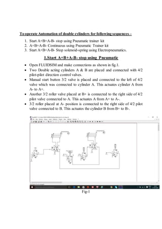
- 1. To operate Automation of double cylinders for following sequences – 1. Start A+B+A-B- stop using Pneumatic trainer kit 2. A+B+A-B- Continuous using Pneumatic Trainer kit 3. Start A+B+A-B- Stop solenoid-spring using Electropneumatics. 1.Start A+B+A-B- stop using Pneumatic  Open FLUIDSIM and make connections as shown in fig.1.  Two Double acting cylinders A & B are placed and connected with 4/2 pilot-pilot direction control valves.  Manual start button 3/2 valve is placed and connected to the left of 4/2 valve which was connected to cylinder A. This actuates cylinder A from A- to A+.  Another 3/2 roller valve placed at B+ is connected to the right side of 4/2 pilot valve connected to A. This actuates A from A+ to A-.  3/2 roller placed at A- position is connected to the right side of 4/2 pilot valve connected to B. This actuates the cylinder B from B+ to B-. Fig-1
- 2. 2. A+B+A-B- Continuous using Pneumatic ď‚· Open FLUIDSIM and make connections as shown in fig.2. ď‚· Two Double acting cylinders A & B are placed and connected with 4/2 pilot-pilot direction control valves. ď‚· 3/2 Roller valve is placed at position A-,B-,A+&B+. ď‚· The 3/2 roller valve at B- is connected to left of 4/2 valve to actuate A+ position of cylinder A. ď‚· 3/2 Roller valve at A+ is then connected to the left side of 4/2 valve to actuate B+ position of cylinder B. ď‚· The 3/2 roller valve at B+ gets active and is connected to the right side of the 4/2 valve to actuate cylinder A to position A-. This moves the cylinder B+ to B- position. ď‚· The above series continues making this a continuous circuit of A+B+A- B-. Fig-2
- 3. 3.Start A+B+A-B- Stop solenoid-spring using Electropneumatics ď‚· Open FLUIDSIM and make connections as shown in fig.3. ď‚· When the start button is pressed , signal reaches solenoid A+ since internal relay IR is normally closed. ď‚· A+ gives signal to A+ which activates solenoid B+ since Internal relay IR is again normally closed. ď‚· Solenoid B+ gives power to B+. B+ and A+ together gives to internal relay IR. ď‚· IR then gives signal to A- solenoid and cylinder A retracts to A- position. ď‚· Since A+ is latched with IR . IR remains in power. IR and A- together gives signal to B- and therefore cylinder B retracts to position B-. Fig-3
- 4. Application- Practical application of this circuit – Say, A represents an arm and B represents wrist, Arm moves ahead, wrist closes, arm comes back and wrist opens. This can be compared to a robot arm, which has to hold a work-piece(say-hot) from a conveyor and place it to another conveyor. The worker has button-based control, to move the arm and place the piece on another conveyor.