session-2_track-6_advanced-bldc-motor-drive.pdf
?
0 likes?55 views

The document provides information about advanced BLDC motor drive and control, including: - An overview of a 3-phase BLDC motor control block diagram showing the main components. - Details about STMicroelectronics products that can be used for BLDC motor control, such as MCUs, gate drivers, power modules, and development tools. - Descriptions of permanent magnet synchronous motors (PMSM) and brushless DC (BLDC) motors, and an explanation of field oriented control (FOC), which is used to control these types of motors.


![? The B-emf constant represents the proportionality constant between the mechanical motor speed and the
amplitude of the B-emf induced into motor phases:
? To measure Ke , usually is sufficient to turn
the motor with your hands (or using drill or
another motor mechanically coupled) and
look with an oscilloscope to phase-to-phase
induced voltage (VBemf )
? If you have no access to the rotor (e.g. in
compressor applications) see next slide
? Measure VBemf frequency (FBemf) and peak-to-peak amplitude (VBemf ¨CA)
? Compute Ke in Vrms / Krpm:
+
-
How To Measure Bemf 1/2
Access to rotor
VBemf = Ke ˇ¤ ¦Řmec
60
]
[
2
2
1000
]
[
?
?
?
?
?
?
?
?
?
Hz
F
number
pairs
pole
peak
to
peak
V
V
K
Bemf
A
Bemf
e](https://image.slidesharecdn.com/session-2track-6advanced-bldc-motor-drive-230301151005-8881a430/85/session-2_track-6_advanced-bldc-motor-drive-pdf-42-320.jpg)
![? If you have no access to rotor (e.g. in compressors)
follow this procedure:
? Configure power stage (see later)
? Configure drive parameters for sensor-less as described in
slides 16-19 but
? Set current ramp initial and final values equal to motor nominal
current value
? Set the speed ramp duration to 5000ms and speed ramp final
value to around 50% of maximum application speed
? Set minimum start-up output speed higher than speed ramp final value
? Configure control stage
? Start the motor ramp-up and look with the oscilloscope to the
voltage between two motor phases
? When the driving signal are switched off, rotor was probably
moving then look to the B-emf
+
-
How To Measure Bemf 2/2
60
]
[
2
2
1000
]
[
?
?
?
?
?
?
?
?
?
Hz
F
number
pairs
pole
peak
to
peak
V
V
K
Bemf
A
Bemf
e
No Access to rotor](https://image.slidesharecdn.com/session-2track-6advanced-bldc-motor-drive-230301151005-8881a430/85/session-2_track-6_advanced-bldc-motor-drive-pdf-43-320.jpg)


session-2_track-6_advanced-bldc-motor-drive.pdf
- 1. Advanced BLDC Motor Drive and Control Giovanni Tomasello ¨C Applications Engineer
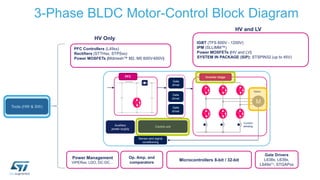
- 2. IGBT (TFS 600V - 1200V) IPM (SLLIMM?) Power MOSFETs (HV and LV) SYSTEM IN PACKAGE (SiP): STSPIN32 (up to 45V) Microcontrollers 8-bit / 32-bit PFC Controllers (L49xx) Rectifiers (STTHxx, STPSxx) Power MOSFETs (Mdmesh? M2, M5 600V-650V) 3-Phase BLDC Motor-Control Block Diagram Gate Drivers L638x, L639x, L649x(1), STGAPxx Op. Amp. and comparators Power Management VIPERxx, LDO, DC-DCˇ Tools (HW & SW) PFC Inverter stage Control unit Gate driver Auxiliary power supply Motor M Sensor and signal conditioning Gate driver Gate driver Current sensing HV Only HV and LV
- 3. Electric Motor: Classification Electric motors AC Synchronous Sinusoidal Permanent Magnet (PMSM) Internal mounted PM Surface mounted PM Wound field Trapezoidal (BLDC) PM Asynchronous (ACIM) Squirrel cage Wound rotor Variable reluctance Switched reluctance Stepper DC (brushed) Universal ? PMSM: 3-phase permanent magnet synchronous motor ? ACIM: 3-phase induction motor Computation intensive Complex driving, requires specific knowledge and/or support Complete ecosystem necessary Requires 3-phase timer + syncˇŻd ADC Limited computation needs Driving method well-known, mastered by customer Light ecosystem Basic ADC/PWM requirement Higher efficiency and/or reliability
- 4. PMSM and BLDC Motors ? Permanent Magnet Synchronous Motor (PMSM) ? Stator is the same as AC IM: three phase windings ? Rotor houses permanent magnets ? on the surface ? Surface Mounted (SM) PMSM ? Buried within the rotor ?Internal (I) PMSM ? Rotation induces sinusoidal Back Electro-Motive Force (BEMF) in motor phases ? Gives best performances (torque steadiness) when driven by sinusoidal phase current Typical b-emf shape Optimum current shape ? Permanent Magnet BrushLess DC motors (BLDC) ? Like PMSM - and despite of their name - require alternating stator current ? Like in PMSM, rotor houses permanent magnets, usually glued on the surface ? Like PMSM, stator excitation frequency matches rotor electrical speed ? Unlike PMSM, rotor spinning induced trapezoidal shaped Back Electro- Motive Force (Bemf) ? Gives best performances (torque steadiness) when driven by rectangular- shaped currents Typical B-emf shape Optimum current shape
- 5. STSPIN32F0 Technical Details ? Package : VFQFPN 7 x 7 x 1.0 - 48L ? Operating voltage from 8V to 45V ? 3-phase gate driver for high performances ? 600mA current capability ? Real-time programmable over current ? Integrated bootstrap diodes ? Cross conduction, under-voltage and temperature protections ? 32-bit STM32F0 MCU with ARM ? Cortex? M0 Core ? STM32F031x6x7 48MHz, 4-Kb SRAM and 32-Kb Flash ? 12-bit ADC ? 1 to 3 shunts FOC supported ? Communication interfaces I2C, UART and SPI ? Complete Development Ecosystem available ? 4x Operational Amplifiers and a Comparator ? On-chip generated supplies for MCU driver and external circuitry ? 3.3V DC/DC buck regulator ¨C Input voltage up to 45V ? 12V LDO linear regulator ? UVLO protection on all power supply voltages ? Embedded Over-Temperature Protection
- 7. Making Your Designs Easier To support STSPIN32F0, a comprehensive set of design tools is available, including: Reference Code Description STEVAL-SPIN3201 STSPIN32F0 evaluation board Three-phase brushless DC motor driver evaluation board ? Input voltage from 8 to 45 V ? Output current up to 15 Arms ? Power stage based on STD140N6F7 MOSFETs ? Sensored or sensorless field-oriented control algorithm with 3-shunt sensing UM2154 User manual for STEVAL-SPIN3201: advanced BLDC controller with embedded STM32 MCU evaluation board STSW-SPIN3201 Firmware example for field oriented motor control (FOC) UM2152 User manual for Getting started with the STSPIN32F0 FOC firmware example STSW-SPIN3201 STSW-STM32100 Library: STM32 PMSM FOC Software Development Kit
- 8. Why FOC? ? Best energy efficiency even during transient operation. ? Responsive speed control to load variations. ? Decoupled control of both electromagnetic torque and flux. ? Acoustical noise reduction due to sinusoidal waveforms. ? Active electrical brake and energy reversal. ?? Clark Park Park -1 Clark -1 Independent control of flux and torque
- 9. FOC Single Motor For Budgetary Applications ? Target applications: ? All those applications where: ? Dynamic performance requirements are moderate ? Quietness of sinusoidal current control (vs six steps drive) is valuable ? Extended speed range is required ? Particularly suitable for pumps, fans and compressors Current Current DW Spray & drain pumps Fridge compressor WM Drain pump
- 10. FOC Single Or Dual Motor For Higher Performance ? Target applications: ? Wide range from home appliances to robotics, where: ? Accurate and quick regulation of motor speed and/or torque is required (e.g. in torque load transient or target speed abrupt variations) ? CPU load granted to motor control must be low, due to other duties Home appliances Industrial motor drives Power tools Games Escalators and elevators Fitness, wellness and healthcare And much much moreˇ
- 11. PMSM FOC Overview ? Field Oriented Control: stator currents (Field) are controlled in amplitude and phase (Orientation) with respect to rotor flux ? current sensing is mandatory (3shunt/1shunt/ICS) ? speed / position sensing is mandatory (encoder/Hall/sensorless alg) ? current controllers needed (PI/D,FF) ? not easyˇ high frequency sinusoidal references + stiff amplitude modulation.. ? reference frame transformation (Clarke / Park) allows to simplify the problem: Te maximized ifˇ ¦µr ¦µs 90el 90el t
- 12. PMSM FOC Overview: Reference Frame Transformations ? Clarke: transforms ia,ib,ic (120ˇă) to i¦Á,i¦Â (90ˇă); (consider that ia+ib+ic=0); ? Park: currents i¦Á,i¦Â , transformed on a reference frame rotating with their frequency, become DC currents iq,id (90ˇă)! ? PI regulators now work efficiently in a ˇ®DCˇŻ domain; their DC outputs, voltage reference vq,vd are handled by the Reverse Park -> v¦Á,v¦Â AC domain 3 2 bs as as i i i i i ? ? ? ? ? ? ia ib ic i¦Á i¦Â r r a ds r r qs i i i i i i ? ? ? ? ? ? ? cos sin sin cos ? ? ? ? i¦Á i¦Â iq id r ds r qs r ds r qs v v v v v v ? ? ? ? ? ? cos sin sin cos ? ? ? ? ? vq vd v¦Á v¦Â
- 13. SMART SHUTDOWN-BKIN, DC V - TEMP Single PMSM FOC ¨C Block Diagram Speed Control FOC Current Control Motor + ¦Řr *,t vds vqs + - - PID PID iqd iq* id* REVERSE PARK + circle limitation vabc ¦Čr el v¦Á¦Â iabc PARK ¦Čr el i¦Á¦Â CLARKE MTPA & FLUX WEAKENING CONTROLLER Speed sensors: Sensorless, Hall, Encoder ROTOR SPEED/POSITION FEEDBACK PID Te* + - Space Vector PWM Current sensors: 3shunt/1shunt/ ICS PHASE CURRENTS FEEDBACK RAMP GENERATOR ¦Řr* Gate drivers Power Bridge ST SLLIMM? IPM ¦Řr DC domain AC domain
- 14. Dual PMSM FOC ¨C Block Diagram Gate drivers Power bridge1 Motor1 va,b,c Speed sensors: Sensorless, Hall, Encoder BKIN Current sensors: 3shunt/1shunt/ICS Power bridge2 Motor2 Speed sensors: Sensorless, Hall, Encoder Current sensors: 3shunt/1shunt/ICS va,b,c BKIN ¦Řr *1 ¦Řr *2 Gate drivers
- 15. Motor Current Sensing ¨C Why? ? The purpose of field oriented control is to regulate the motor phase currents. ? To do this the three motor phase current need to be measured. Measured motor phase current Ia, Ib, Ic FOC Current reference Voltage command PWM duty
- 16. Current Sensing Topologies ? To measure the motor phase currents a conditioning network is required. ? The STM32 FOC SDK supports three current sensing network ? Insulated current sensor (ICS) ? Three shunts ? Single shunt Three shunts Single shunt Insulated current sesor (ICS) Cost optimized Best quality
- 17. Current Sensing Topologies ? According to the HW the current sensing topology can be selected in the power stage scetion of Workbench Three shunts Single shunt Insulated current sesor (ICS)
- 18. STM32 PMSM FOC SDK v4.3 STM32 PMSM FOC SDK v4.3 ? STSW-STM32100 - includes the PMSM FOC FW library, ST MC Workbench (GUI) and Motor Profiler (GUI), allowing the user to evaluate ST products in applications driving single or dual Field Oriented Control of 3-phase Permanent Magnet motors (PMSM), featuring STM32F3xx, STM32F4xx, STM32F0xx, STM32F1xx, STM32F2xx
- 19. Feature Set According To The Micro 1shunt Flux Weakening IPMSM MTPA Feed Forward Sensor-less (STO + PLL) Sensor-less (STO + Cordic) Encoder Hall sensors Startup on-the-fly ST MC Workbench support USART based com protocol add-on Max FOC(2) F100 ~11kHz F0xx ~12kHz 3shunt F0 supported ICS FreeRTOS Max FOC(2) ~23kHz Digital PFC(3) Dual FOC Max FOC(2) F103 ~23kHz F2xx ~40kHz Max Dual FOC(2) F103 ~20kHz F2xx ~36kHz STM32F103x HD/XL, STM32F2xx STM32F103x LD/MD Motor Control Firmware Library STM32F100x, STM32F0xx STM32F4xx, STM32F3xx New Motor Profiler HFI(1) Max FOC(2) F3xx ~ 30kHz F4xx ~50kHz Max Dual FOC(2) F3xx ~27kHz F4xx~45kHz (1) High Frequency Injection (2) Max FOC estimated in sensorless mode (3) STM32F103xC/D/E/F/G and STM32F303xB/C ??? ???? = ??? ???? ????????? ????
- 20. STM32 FOC SDK ¨C Lab Session Tools: configuration with PC SW ˇ®STMCWBˇŻ, ˇ®Motor ProfilerˇŻ, IDEs
- 21. Motor Control ¨C SDK ¨C Workflow Setup the HW Use Motor specs or Identify the motor with Motor Profiler Finalize the project with Workbench Debug and Real time monitoring
- 22. Motor Control ¨C SDK ¨C Workflow 1/4 ? First step ? Setup the Hardware, according the user's targets it is possible to choose the more suitable HW among the different ST ˇ°ready-to-startˇ± evaluation boards. ? Setup them according the specification stated in each related user manual. ? Connect the board together (if required), power supply and plug your motor.
- 23. Flexible MC Platform MC Connector Full set of control board featuring all ST MCUs Full set of Power board featuring Power Transistor, IPM, MC Driver ICs. + X-NUCLEO-IHM09M1 Connector Adapter NUCLEO-XX Control board STM32XX-EVAL Control board STEVAL-XX Power board
- 24. Motor Control ¨C SDK ¨C Workflow 2/4 ? When the hardware is ready, if the user does not know the motor parameters, he can identify the motor. ? How? Using the Motor Profiler!!
- 25. Motor Profiler
- 26. Set Up Motor Parameters ? ST MC Workbench ¨C Motor section contains: ? Motor parameters ? Motor sensor parameters ? For a custom project, the user can set all the parameters.
- 27. Setup Motor Profiler ? ˇ°Select Boardsˇ± button and a list of supported boards will be shown. The Motor Profiler feature can be used only in the systems listed there.
- 28. Setup Motor Profiler Parameters set by the user: ? Motor pole pairs (Mandatory) ? Maximum application speed ? Not mandatory, if not selected, the Motor Profiler will try to reach the maximum allowed speed. ? Maximum Peak Current ? The maximum peak current delivered to the motor ? Expected bus voltage provided to the system. ? Selecting the kind of Motor ? Surface Permanent Magnet motor SM-PMSM or Internal Permanent Magnet motor I-PMSM In this last case is necessary to provide also the Ld/Lq ratio as input. SM-PMSM I-PMSM
- 29. Setup Motor Profiler ? Connect the HW chosen to the PC ? Click on the ˇ°Connectˇ± button ? If the communication has succeed ? Click on the ˇ°Profileˇ± button
- 30. Run Motor Profiler ? Procedure will end in about 60 seconds. Motor stopped ? Rs measurement ? Ls measurement ? Current regulators set-up Open loop ? Ke measurement ? Sensorless state observer set-up ? Switch over Closed loop ? Friction coefficient measurement ? Moment of inertia measurement ? Speed regulator set-up
- 31. Motor Profiler Complete ? At the end of the procedure, the measured parameters will be shown on a dedicated window. ? It is possible to import them on the workbench project and save them for later use.
- 32. Motor Identified ? Motor Identified: user can start and stop the motor thorough ˇ°Startˇ± and ˇ°Stopˇ± button. ? it is possible to create ST MC Workbench new project with the profiled motor ,clicking ˇ°New Projectˇ±, in the Motor section the user can find
- 33. Motor Profiler ? The Motor Profiler algorithm is intended to be used for a fast evaluation of the ST three phase motor control solution (PMSM) ? Motor Profiler can be used only using compatible ST evaluation boards. Choosing the best ST HW according to the motor characteristics. ? The measurement precision can not be like when an instrumentation is used. ? Motor Profiler measurement cannot become significant for some motors, please see the limits reported in the software tool.
- 34. How To Manually Measure Motor Parameters
- 35. PMSM - Motor Parameters STMCWB ¨C Motor section contains: ? Electrical motor parameters ? Motor sensor parameters
- 36. PMSM - Electrical Motor Parameters ? Select either Internal PMSM or Surface Mounted PMSM according to the magnetic structure of your motor ? If you donˇŻt have this information you need to measure both Ld and Lq inductance for verifying it ? IF SM-PMSM 2*(Lq-Ld)/(Ld+Lq) <15% ? See next slides for learning how to measure motor inductances
- 37. PMSM ¨C Pole Pairs Number ? Usually, itˇŻs provided by motor supplier ? In case itˇŻs not or if youˇŻd like to double check it ? Connect a DC power supply between two (of the three) motor phases and provide up to 5% of the expected nominal DC bus voltage (you may also set current protection to nominal motor current) ? Rotate the motor with hands (you should notice some resistance) ? The number of rotor stable positions in one mechanical turn represents the number of pole pairs + - DC voltage source
- 38. How To Measure Motor Inductance 1/3 ? In case of SM-PMSM, the phase inductance does not depends on rotor position. In this case Ls notation is also utilized ? If you have a RLC meter ? Connect it phase-to-phase and measure series R and L at 100Hz (make sure rotor doesnˇŻt move) ? Repeat 4*number of pole pairs times: ? Turn the rotor by 360/(4*number of pole pairs) mechanical degrees, ? Wait for new measurements to get stable ? Read new measurement ? IF In this case, in the Workbench you can use for Rs and Ls half of the values read on the instrument STMCWB requires phase to neutral value + - 2*(Lq-Ld)/(Ld+Lq) <15% SM - PMSM RLC meter f = 100Hz with RLC meter
- 39. ? IF In the Workbench you can set Ld equal to minimum measured value divided by 2 (STMCWB requires phase to neutral value), set Lq equal to maximum measured value divided by 2 Set Rs equal to average measured resistance divided by two + - RLC meter f = 100Hz 2*(max(L)-min(L))/(max(L)+min(L)) > 15% I - PMSM with RLC meter How To Measure Motor Inductance 1/3
- 40. ? If you donˇŻt have a RLC meter ? For Rs, measure the DC stator resistance phase-to-phase and divide it by two ? Once measured Rs, itˇŻs necessary to measure L/R time constant between two motor phases. ? Connect DC voltage between two motor phases ? Connect oscilloscope ? Increase the voltage up to the value where the current equals the nominal one, rotor with align ? DonˇŻt move rotor any more ? Disable current protection of DC voltage source ? Unplug one terminal of the voltage source cable without switching it off ? Plug the voltage source rapidly and monitor on the scope the voltage and current waveform ? The measurement is good if the voltage is a nice step and the current increase like IˇŢ * (1-e- t *L/R) ? Measure the time required to current waveform to rise up to 63% ? This time is Ld/Rs constant. Multiply it by Rs and youˇŻll get Ld value V V IˇŢ ¦Ó = L/R 0.63*IˇŢ + - DC voltage source How To Measure Motor Inductance 2/3 without RLC meter I
- 41. ? Once measured Rs, itˇŻs necessary to measure Lq/Rs time constant between two motor phases. ? Connect DC voltage between two motor phases ? Connect oscilloscope ? Increase the voltage up to the value where the current equals the nominal one, rotor with align ? Lock the rotor in this position (so that it can not move anymore) ? Change DC voltage source connections as shown in the second figure ? Unplug one terminal of the voltage source cable without switching it off ? Plug the voltage source rapidly and monitor on the scope the voltage and current waveform ? The measurement is good if the voltage is a step and the current increase like IˇŢ * (1-e- t *L/R) ? Measure the time required to current waveform to rise up to 63% ? This time is Lq/Rs constant. Multiply it by 2Rs/3 and youˇŻll get Lq value V IˇŢ ¦Ó = L/R 0.63*IˇŢ + - How To Measure Motor Inductance 3/3 + - V I DC voltage source DC voltage source without RLC meter
- 42. ? The B-emf constant represents the proportionality constant between the mechanical motor speed and the amplitude of the B-emf induced into motor phases: ? To measure Ke , usually is sufficient to turn the motor with your hands (or using drill or another motor mechanically coupled) and look with an oscilloscope to phase-to-phase induced voltage (VBemf ) ? If you have no access to the rotor (e.g. in compressor applications) see next slide ? Measure VBemf frequency (FBemf) and peak-to-peak amplitude (VBemf ¨CA) ? Compute Ke in Vrms / Krpm: + - How To Measure Bemf 1/2 Access to rotor VBemf = Ke ˇ¤ ¦Řmec 60 ] [ 2 2 1000 ] [ ? ? ? ? ? ? ? ? ? Hz F number pairs pole peak to peak V V K Bemf A Bemf e
- 43. ? If you have no access to rotor (e.g. in compressors) follow this procedure: ? Configure power stage (see later) ? Configure drive parameters for sensor-less as described in slides 16-19 but ? Set current ramp initial and final values equal to motor nominal current value ? Set the speed ramp duration to 5000ms and speed ramp final value to around 50% of maximum application speed ? Set minimum start-up output speed higher than speed ramp final value ? Configure control stage ? Start the motor ramp-up and look with the oscilloscope to the voltage between two motor phases ? When the driving signal are switched off, rotor was probably moving then look to the B-emf + - How To Measure Bemf 2/2 60 ] [ 2 2 1000 ] [ ? ? ? ? ? ? ? ? ? Hz F number pairs pole peak to peak V V K Bemf A Bemf e No Access to rotor
- 44. ? Max rated speed (rpm) ? Should be provided by motor producer (if not, set it to max application speed) ? Maximum motor rated speed above which motor can get damaged ? Maximum application speed must be lower than this value ? Nominal current (in A, 0-to-peak) ? Motor rated current, must be provided by motor producer ? It will be used to limit the imposed motor phase current during normal operation ? Nominal DC voltage ? Nominal DC bus voltage from which the motor should run, must be provided by motor producer ? Demagnetizing current ? Rotor demagnetizing current, may be provided by motor producer (if not use default value, i.e. motor nominal current) ? Used to limit the amount of target negative Id during flux weakening Other Electrical Parameters
- 45. Motor Control ¨C SDK ¨C Workflow 3/4 ? With Motor Profiler the motor is running but the user can develop his own code! ? Finalize the MC project using Workbench and use your favorite IDE to develop your code. MC Workbench
- 46. Create A New WB Project Based On The ST Evaluation Board Choose: New Project
- 47. Create A New WB Project Based On The ST Evaluation Board 1. Applications 1 Choose:
- 48. Create A New WB Project Based On The ST Evaluation Board 2. Single or dual motor Choose: 2
- 49. Create A New WB Project Based On The ST Evaluation Board 3. Board approach: ? Choose if you are using Inverter, MC Kit or Power plus Control boards. ? Select the board used or create your own custom board. Choose: 3
- 50. Create A New WB Project Based On The ST Evaluation Board 4. Motor: Choose motor from a motor database. (You can save your motor parameters from your project.) Choose: 4
- 51. Create A New WB Project Based On An Example ? Choose the WB example project that best fits your needs. ? Choose the one with the same name of the ST evaluation board you are using, or ? choose the one with the same microcontroller you are using.
- 52. Create A New WB Project ? Starting from the board selection or example project, the control stage parameters will be populated with the correct values. ? For a custom project, the user can set all the parameters. STM32303E-EVAL
- 53. Set Up Power Stage ? Starting from the board selection or example project, the power stage parameters will be populated with the correct values. ? For a custom project, the user can set all the parameters.
- 54. Set Up Drive Parameters ? Starting from the board selection according to the chosen application, drive parameters will be populated with the correct values. ? For a custom project, the user can set all the parameters. Applications
- 55. Parameter Generation ? Once all the parameters have been entered in the ST MC Workbench, select the output path in the option form and choose ˇ®SystemDriveParamsˇŻ present in the FW working folder. ? Click on the ˇ®GenerationˇŻ button to configure the project.
- 56. Compile And Program The MCU ? Run the IAR Embedded Workbench. ? Open the IAR workspace (located in ProjectEWARM) folder according to the microcontroller family (e.g. STM32F10x_Workspace.eww for STM32F1). ? Select the correct user project from the drop-down menu according to the control stage used (e.g. STM32F10x_UserProject - STM3210B-EVAL). ? Compile and download. Compile & program Select project
- 57. Compile And Program The MCU ? Optionally, run Keil uVision. ? Open the Keil workspace (located in ProjectMDK-ARM) folder according to the microcontroller family (e.g. STM32F10x_Workspace.uvmpw for STM32F1). ? Select the proper user project from the drop-down menu according to the control stage used (e.g. STM3210B-EVAL). ? Compile and download. Select project Compile Program
- 58. Motor Control ¨C SDK ¨C Workflow 4/4 ? Finally the user can send commands (e.g. start, stop, execRamp, ˇ) via serial communication. ? Use the Workbench for debugging and real time communication.
- 59. Run The Motor ? Arrange the system for running the motor: ? Connect the control board with the power board using the MC cable. ? Connect the motor to the power board. ? Connect the power supply to the power board and turn on the bus. ? If the board is equipped with the LCD: ? Press joystick center on Fault Ack button to reset the faults. ? Press joystick right until the Speed controller page is reached. ? The press joystick down to reach the Start/Stop button. ? Press the center of the joystick to run the motor.
- 60. ? Optionally you can start the motor using the ST MC Workbench. ? Connect the PC to the control board with the USB to RS-232 dongle (and a null modem cable). ? Open the Workbench project used to configure the firmware and click on Monitor button. ? Select the COM port and click Connect button. This establish the communication with the firmware. ? To clear the fault, click Fault Ack and then Start Motor button to run the motor. Monitor Select COM port Connect Fault ACK Start Run The Motor
- 61. State Observer: Startup Procedure ? The sensorless algorithm is a bemf observer, so the motor should rotate to produce BEMF. ThatˇŻs why a startup procedure is required. Startup needs to be tuned (depend on inertia, load..) ? Two options of settings: basic and advanced Basic Advanced
- 62. How To Customize The Sensor-Less Start-Up ? Set current ramp initial and final values equal to motor nominal current value / 2 (if load is low at low speed, otherwise it can be set up to 0.8-1.0 times nominal current value) ? Set speed ramp final value to around 30% of maximum application speed ? According to motor inertia it may be required to increase the speed ramp duration ? Set minimum start-up output speed to 15% of maximum application speed (if required, decreased it later) ? Set estimated speed band tolerance lower limit to 93.75% ? Enable the alignment at the beginning of your development (duration 2000ms, final current ramp value from 0.5 to 1 times motor nominal current according to load) Basic
- 63. Startup Procedure: Basic, Acceleration Speed ramp final value Current Speed time time Current ramp duration Speed ramp duration Current ramp final value Current ramp initial value
- 64. Startup Procedure: Basic, Current Speed ramp final value Current Speed time time Current ramp duration Speed ramp duration Current ramp final value Current ramp initial value
- 65. Startup Procedure: Advanced ? The programmed rev-up sequence is composed by a number of stages; for each stage is possible to define the duration, the final torque reference and the final speed of the virtual sensor. ? It is possible to define the starting electrical angle. ? It is possible to set step variation in the current using duration zero. Stage 0 Stage 1 Stage 2 time time Duration Stage 0 Torque ref. Stage 0 Final speed Stage 0 Current Speed
- 66. ? Problem: ˇ®SW errorˇŻ fault message appears and the motor do not even try to start ? Source: the FOC execution rate is too high and computation can not be ended in time ? Solution: In Drive settings, decrease ratio between PWM frequency and Torque and flux regulator execution rate (e.g. increasing Torque and flux regulator execution rate by one ) ? Problem: ˇ®Over-currentˇŻ fault message appears and the motor do not even try to start ? 1st possible source: wrong current sensing topology has been selected in power stage ? current sensing ? Solution: select right current sensing configuration ? 2nd possible source: wrong current sensing parameters ? Solution: check power stage parameters ? 3rd possible source: current regulation loop bandwidth is too high for this HW ? Solution: in drive parameters ? drive settings decrease current regulation bandwidth (normally down to 2000 rad/sec for 3shunt topology and 1000 rad/s for single shunt topology) ? Typical current regulation loop bandwidth max values are 4500 rad/sec for 1 shunt, 9000 rad/sec for 3-shunt Troubleshooting
- 67. ? Problem: Motor initially moves but then doesnˇŻt rev-up, then fault message ˇ®Rev-up failureˇŻ appears ? Source: typically this happens cause the current provided to the motor is not enough for making it accelerate so fast ? 1st possible solution: decrease acceleration rate by increasing Start-up parameters ? speed ramp duration (being Start-up parameters ? speed ramp final value set to about 30% of maximum application speed) ? 2nd possible solution: increase start-up current by increasing current ramp initial and final values up to motor ? nominal current ? Enabling ˇ®Alignment phaseˇŻ (at least at the beginning of the development) makes start-up more deterministic, use around 2000ms, half of nominal current as first settings ? Problem: The rotor moves and accelerate following the ramp-up profile but then it stops and the fault message ˇ®Rev-up failureˇŻ appears (a mix of following problem sources can be occurring): ? 1st possible source: Observer gain G2 is too high and this makes speed reconstruction a bit noisy (never recognized as reliable). A mix of following solutions could be required: ? 1st possible solution: decrease observer gain G2 by successive steps: /2, /4, /6, /8 ? 2nd possible solution: Enlarge Drive parameters? Speed/position feedback management ? variance threshold so as to make rotor locked check less ˇ®demandingˇŻ. (up to 80% for PLL and 400% for CORDIC) ? 2nd possible source: the ˇ°windowˇ± where the reliability of the estimation is checked is too small ? 1st possible solution: increase speed ramp final value to around 40% of maximum application speed ? 2nd possible solution: decrease minimum start-up output speed to 10% of maximum application speed Troubleshooting
- 68. ? Problem: The rotor moves and accelerate following the ramp-up profile but then it stops and the fault message ˇ®Speed feedbackˇŻ appears ? Use speed ramps: having a target speed gently going from the start-up output speed to the final target will avoid abrupt variations of torque demand that could spoil B-emf estimation ? A mix of following problem sources can be occurring: ? 1st possible source: Observer gain G2 is too high and this makes speed reconstruction a bit noisy (for the selected speed PI gains). A mix of following solutions could be required: ? 1st possible solution: decrease observer gain G2 by successive steps: /2, /4, /6, /8 ? 2nd possible solution: Run motor in torque mode, if trouble doesnˇŻt exist in torque mode, it means speed regulator gains are not optimal try changing them ? 2nd possible source: frequent situation when the start-up has been validated too early ? Solution: Try increasing Start-up parameters ? consecutive successful start-up output test (normally to not more than 4-5) being minimum start-up output speed set to 15% of maximum application speed (if required, decreased it later) ? Problem: motor runs but current are not sinusoidal at all ? 1st possible source: speed PI gains are not good ? Solution: decrease Kp gain (and act on Ki evaluating speed regulation over/under shooting during transients) Troubleshooting
- 69. Use DAC Channels ? DAC functionality can help to debug and tune the application. Enabling Selection with WB Selection with LCD
- 70. Use DAC Channels ? Typical DAC waveforms of tuned system ? Green: phase A motor current ? Yellow: DAC ch1 (Ia) ? Pink: DAC ch2 (Ib) ? Green: phase A motor current ? Yellow: DAC ch1 (Obs. BEMF Alpha) ? Pink: DAC ch2 (Obs. BEMF Beta)
- 71. Thank You!