


More Related Content
Similar to Unit-2 Look Angle Determination.ppt inSC (20)
More from bandiprathyu (20)


Recently uploaded (20)


Unit-2 Look Angle Determination.ppt inSC
- 1. Unit-II Look Angle Determination Mrs B.Prathyusha Asst.Professor Department of ECE
- 2. Reference Satellite Communications, ŌĆØ Timothy Pratt ,Jeremy Allnutt ŌĆ£, Third Edition, Wiley 2020.
- 3. Learning Outcome ŌĆó Students will be able to determine the look angles of a satellite.
- 4. Contents ŌĆó Look Angle Determination : Azimuthal Angle, Elevation Angle ŌĆó Subsatellite Point :Nadir Direction, Zenith Direction ŌĆó Azimuthal Angle Measurement ŌĆó Elevation Angle Measurement ŌĆó Visibility Test
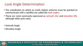
- 5. Look Angle Determination ŌĆó The coordinates to which an earth station antenna must be pointed to communicate with a satellite are called the look angles. ŌĆó These are most commonly expressed as azimuth (Az) and elevation (El), although other pairs exist. ŌĆó Azimuth Angle ŌĆó Elevation Angle
- 6. ŌĆó Generally, the values of these angles change for non-geostationary orbits. Whereas, the values of these angles donŌĆÖt change for geostationary orbits. Because, the satellites present in geostationary orbits appear stationary with respect to earth. ŌĆó These two angles are helpful in order to point at the satellite directly from the earth station antenna. So, the maximum gain of the earth station antenna can be directed at satellite.
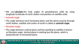
- 7. ŌĆó We can calculate the look angles of geostationary orbit by using longitude & latitude of earth station and position of satellite orbit. ŌĆó Azimuth Angle ŌĆó The angle between local horizontal plane and the plane passing through earth station, satellite and center of earth is called as azimuth angle. ŌĆó Elevation Angle ŌĆó The angle between vertical plane and line pointing to satellite is known as Elevation angle. Vertical plane is nothing but the plane, which is perpendicular to horizontal plane.
- 8. Azimuth is measured eastward (clockwise) from geographic north to the projection of the satellite path on a (locally) horizontal plane at the earth station. Elevation is the angle measured upward from the local horizontal plane at the earth station to the satellite path.
- 9. ŌĆó Navigation around the earthŌĆÖs oceans became more precise when the surface of the globe was divided up into a grid-like structure of orthogonal lines: latitude and longitude. ŌĆó Latitude is the angular distance, measured in degrees, north or south of the equator and longitude is the angular distance, measured in degrees, from a given reference longitudinal line. ŌĆó England drew its reference zero longitude through Greenwich, a town close to London, England, and France, not surprisingly, drew its reference longitude through Paris, France.
- 10. ŌĆó When GEO satellite systems are registered in Geneva, their (subsatellite) location over the equator is given in degrees east to avoid confusion. Thus, the INTELSAT primary location in the Indian Ocean is registered at 60┬░E and the primary location in the Atlantic Ocean at 335.5┬░E (not 24.5┬░W). ŌĆó Earth stations that communicate with satellites are described in terms of their geographic latitude and longitude when developing the pointing coordinates that earth station must use to track the apparent motion of the satellite.
- 11. The Subsatellite Point ŌĆó The subsatellite point is the location on the surface of the earth that lies directly between the satellite and the center of the earth. ŌĆó It is the nadir pointing direction from the satellite and, for a satellite in an equatorial orbit, it will always be located on the equator. ŌĆó Since geostationary satellites are in equatorial orbits and are designed to stay stationary over the earth, it is usual to give their orbital location in terms of their subsatellite point.
- 12. ŌĆó To an observer of a satellite standing at the subsatellite point, the satellite will appear to be directly overhead, in the zenith direction from the observing location. ŌĆó The zenith and nadir paths are therefore in opposite directions along the same path ŌĆó Designers of satellite antennas reference the pointing direction of the satelliteŌĆÖs antenna beams to the nadir direction.
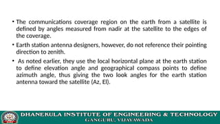
- 13. ŌĆó The communications coverage region on the earth from a satellite is defined by angles measured from nadir at the satellite to the edges of the coverage. ŌĆó Earth station antenna designers, however, do not reference their pointing direction to zenith. ŌĆó As noted earlier, they use the local horizontal plane at the earth station to define elevation angle and geographical compass points to define azimuth angle, thus giving the two look angles for the earth station antenna toward the satellite (Az, El).
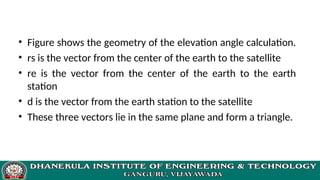
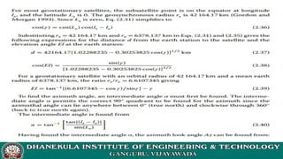
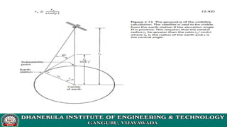
- 15. ŌĆó Figure shows the geometry of the elevation angle calculation. ŌĆó rs is the vector from the center of the earth to the satellite ŌĆó re is the vector from the center of the earth to the earth station ŌĆó d is the vector from the earth station to the satellite ŌĆó These three vectors lie in the same plane and form a triangle.
- 16. ŌĆó The central angle ╬│ measured between re and rs is the angle between the earth station and the satellite ŌĆó Žł is the angle (within the triangle) measured from re to d. ŌĆó Defined so that it is non-negative, ╬│ is related to the earth station north latitude Le (i.e., Le is the number of degrees in latitude that the earth station is north from the equator) and west longitude le (i.e., le is the number of degrees in longitude that the earth station is west from the Greenwich meridian) and the subsatellite point at north latitude Ls and west longitude ls by
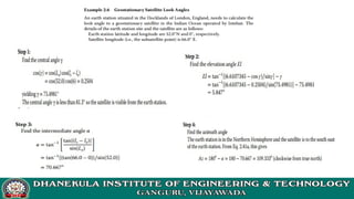
- 18. Azimuth Angle Calculation ŌĆó Since the earth station, the center of the earth, the satellite, and the subsatellite point all lie in the same plane, the azimuth angle Az from the earth station to the satellite is the same as the azimuth from the earth station to the subsatellite point. ŌĆó This is more difficult to compute than the elevation angle because the exact geometry involved depends on whether the subsatellite point is east or west of the earth station, and in which of the hemispheres the earth station and the subsatellite point are located.
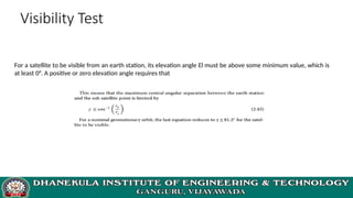
- 21. Visibility Test For a satellite to be visible from an earth station, its elevation angle El must be above some minimum value, which is at least 0┬░. A positive or zero elevation angle requires that
- 25. Any Queries ? Thank You