а№Ғаёҡаёҡаёқаё¶аёҒаё«аёұаё”аё—аёөа№Ҳ 3 аёҒаёІаёЈаёүаёІаёўаё аёІаёһаёӯаёӯа№ӮаёҳаёҒаёЈаёІаёҹаёҙаёҒ
2 likes11,286 views


More Related Content
What's hot (20)
Viewers also liked (20)


More from аёҷаёІаёўаёӘаёёаёЈаёһаёұаёҷаёҳа№Ң аёЈаёұаёҒаё©аёІаёһаёЈаёІаё«аёЎаё“а№Ң (11)


а№Ғаёҡаёҡаёқаё¶аёҒаё«аёұаё”аё—аёөа№Ҳ 3 аёҒаёІаёЈаёүаёІаёўаё аёІаёһаёӯаёӯа№ӮаёҳаёҒаёЈаёІаёҹаёҙаёҒ
- 1. Мэ NWPМэ JuneМэ2007Мэ VersionМэ0.5Мэ 85МэOrthographicМэProjectionМэ а№ҒаёҡаёҡаёқпңғаёҒаё«аёұаё” 1. аёҲаёҮаёҡаёӯаёҒаёҠаёҷаёҙаё”аёӮаёӯаёҮа№ҖаёӘпңӢаёҷаё—аёөа№Ҳаёӯаёўаё№пңҠаёҡаёҷаё§аёұаё•аё–аёёаё§пңҠаёІа№Җаёӣпң’аёҷа№ҖаёӘпңӢаёҷ normal line, inclined line аё«аёЈаё·аёӯ oblique line 2. аёҲаёҮаёҡаёӯаёҒаёҠаёҷаёҙаё”аёӮаёӯаёҮа№ҖаёӘпңӢаёҷаё—аёөа№Ҳаёӯаёўаё№пңҠаёҡаёҷаё§аёұаё•аё–аёёаё§пңҠаёІа№Җаёӣпң’аёҷа№ҖаёӘпңӢаёҷ normal line, inclined line аё«аёЈаё·аёӯ oblique line 1-2 1-3 3-4 4-5 2-6 6-7 7-8 8-2 1-2 1-3 3-4 4-5 5-6 6-7 7-8 8-6
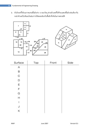
- 2. Мэ NWPМэ JuneМэ2007Мэ VersionМэ0.5Мэ 86Мэ FundamentalМэofМэEngineeringМэDrawingМэ 3. аё•аёұаё§аёӯаёұаёҒаё©аёЈаё—аёөа№Ҳа№ғаё«пңӢаёҡаёҷаё аёІаёһа№Ғаё—аёҷаёһаё·а№үаёҷаёңаёҙаё§аё•пңҠаёІаёҮ а№Ҷ аёӮаёӯаёҮаё§аёұаё•аё–аёё аёӘпңҠаё§аёҷаё•аёұаё§а№ҖаёҘаёӮаё—аёөа№Ҳа№ғаё«пңӢаёҒа№ҮаёҲаё°а№ҒаёӘаё”аёҮаёһаё·а№үаёҷаёңаёҙаё§а№ҖаёҠпңҠаёҷа№Җаё”аёөаёўаё§аёҒаёұаёҷ аёҲаёҮаёҷа№ҚаёІаё•аёұаё§а№ҖаёҘаёӮไаёӣа№Җаё•аёҙаёЎаёҘаёҮа№ғаёҷаёҠпңҠаёӯаёҮаё§пңҠаёІаёҮа№ғаё«пңӢаёӘаёӯаё”аё„аёҘпңӢаёӯаёҮаёҒаёұаёҡаёһаё·а№үаёҷаёңаёҙаё§аё—аёөа№Ҳа№Җаё«а№Үаёҷа№ғаёҷаё аёІаёһаёӘаёІаёЎаёЎаёҙаё•аёҙ Surface Top Front Side A B C D E F G H I J K
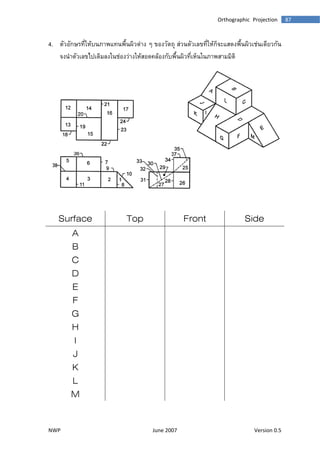
- 3. Мэ NWPМэ JuneМэ2007Мэ VersionМэ0.5Мэ 87МэOrthographicМэProjectionМэ 4. аё•аёұаё§аёӯаёұаёҒаё©аёЈаё—аёөа№Ҳа№ғаё«пңӢаёҡаёҷаё аёІаёһа№Ғаё—аёҷаёһаё·а№үаёҷаёңаёҙаё§аё•пңҠаёІаёҮ а№Ҷ аёӮаёӯаёҮаё§аёұаё•аё–аёё аёӘпңҠаё§аёҷаё•аёұаё§а№ҖаёҘаёӮаё—аёөа№Ҳа№ғаё«пңӢаёҒа№ҮаёҲаё°а№ҒаёӘаё”аёҮаёһаё·а№үаёҷаёңаёҙаё§а№ҖаёҠпңҠаёҷа№Җаё”аёөаёўаё§аёҒаёұаёҷ аёҲаёҮаёҷа№ҚаёІаё•аёұаё§а№ҖаёҘаёӮไаёӣа№Җаё•аёҙаёЎаёҘаёҮа№ғаёҷаёҠпңҠаёӯаёҮаё§пңҠаёІаёҮа№ғаё«пңӢаёӘаёӯаё”аё„аёҘпңӢаёӯаёҮаёҒаёұаёҡаёһаё·а№үаёҷаёңаёҙаё§аё—аёөа№Ҳа№Җаё«а№Үаёҷа№ғаёҷаё аёІаёһаёӘаёІаёЎаёЎаёҙаё•аёҙ Surface Top Front Side A B C D E F G H I J K L M
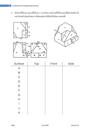
- 4. Мэ NWPМэ JuneМэ2007Мэ VersionМэ0.5Мэ 88Мэ FundamentalМэofМэEngineeringМэDrawingМэ 5. аё•аёұаё§аёӯаёұаёҒаё©аёЈаё—аёөа№Ҳа№ғаё«пңӢаёҡаёҷаё аёІаёһа№Ғаё—аёҷаёһаё·а№үаёҷаёңаёҙаё§аё•пңҠаёІаёҮ а№Ҷ аёӮаёӯаёҮаё§аёұаё•аё–аёё аёӘпңҠаё§аёҷаё•аёұаё§а№ҖаёҘаёӮаё—аёөа№Ҳа№ғаё«пңӢаёҒа№ҮаёҲаё°а№ҒаёӘаё”аёҮаёһаё·а№үаёҷаёңаёҙаё§а№ҖаёҠпңҠаёҷа№Җаё”аёөаёўаё§аёҒаёұаёҷ аёҲаёҮаёҷа№ҚаёІаё•аёұаё§а№ҖаёҘаёӮไаёӣа№Җаё•аёҙаёЎаёҘаёҮа№ғаёҷаёҠпңҠаёӯаёҮаё§пңҠаёІаёҮа№ғаё«пңӢаёӘаёӯаё”аё„аёҘпңӢаёӯаёҮаёҒаёұаёҡаёһаё·а№үаёҷаёңаёҙаё§аё—аёөа№Ҳа№Җаё«а№Үаёҷа№ғаёҷаё аёІаёһаёӘаёІаёЎаёЎаёҙаё•аёҙ Surface Top Front Side A B C D E F G H I J K
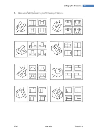
- 5. Мэ NWPМэ JuneМэ2007Мэ VersionМэ0.5Мэ 89МэOrthographicМэProjectionМэ 6. аёҲаёҮ๶ДаёҘаё·аёӯаёҒаё аёІаёһаё—аёөа№ҲаёӣаёЈаёІаёҒаёҺа№ҖаёЎаё·а№ҲаёӯаёЎаёӯаёҮаё§аёұаё•аё–аёёаё•аёІаёЎаё—аёҙаёЁаё—аёІаёҮаҫәаёӯаёҮаёҘаё№аёҒаёЁаёЈа№ғаё«пңӢаё–аё№аёҒаё•ҪИӢаёӯаёҮ