


![CCNA3-13 Chapter 6
• Router-on-a-stick Inter-VLAN Routing:
• Create the subinterface:
• The syntax for the subinterface is always the physical
interface followed by a period and a subinterface
number.
• The subinterface number is configurable, but it is
typically associated to reflect the VLAN number.
R1(config)#interface [interface].nn
NOTE: The management VLAN must also be
configured if you wish to use it on multiple switches
that are not directly connected by trunk links.
Interfaces and Subinterfaces](https://image.slidesharecdn.com/explswchapter06intervlan-130714153734-phpapp02/85/Expl-sw-chapter_06_inter_vlan-13-320.jpg)

![CCNA3-15 Chapter 6
• Router-on-a-stick Inter-VLAN Routing:
• Assign an IP Address:
• The IP Address assigned here will become the default
gateway for that VLAN.
R1(config-subif)#ip address [address] [mask]
Interfaces and Subinterfaces](https://image.slidesharecdn.com/explswchapter06intervlan-130714153734-phpapp02/85/Expl-sw-chapter_06_inter_vlan-15-320.jpg)


More Related Content
What's hot (20)
Similar to Expl sw chapter_06_inter_vlan (20)


More from aghacrom (11)


Expl sw chapter_06_inter_vlan
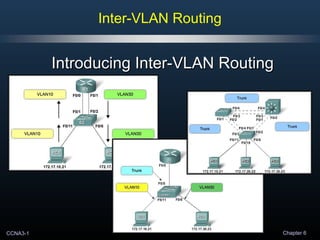
- 1. CCNA3-1 Chapter 6 Inter-VLAN Routing Introducing Inter-VLAN RoutingIntroducing Inter-VLAN Routing
- 2. CCNA3-2 Chapter 6 • What is Inter-VLAN Routing? • Setiap VLAN memiliki unique broadcast domain. • Computers yang terdiri dari VLANs yang terpisah, secara default, tidak dapat berkomunikasi. • Setiap VLAN memiliki unique IP subnetwork. • Agar VLANs dapat saling berkomunikasi, kita membutuhkan router untuk menghubungkan broadcast domains dan unique IP subnetworks yang berbeda. • Oleh karena itu Inter-VLAN routing, merupakan sebuah process untuk melakukan forwarding traffic dari VLAN yang satu ke VLAN lainnya dengan menggunakan router. Introducing Inter-VLAN Routing
- 3. CCNA3-3 Chapter 6 • Ada beberapa Methods dari Inter-Vlan Routing ini, yaitu: 1. Traditional Inter-VLAN Routing. 2. Router-on-a-stick Inter-VLAN Routing. 3. Switch Based Inter-VLAN Routing. Introducing Inter-VLAN Routing
- 4. CCNA3-4 Chapter 6 • Traditional Inter-VLAN Routing: • One router interface per VLAN. Introducing Inter-VLAN Routing VLANVLAN TaggedTagged VLANVLAN TaggedTagged Internally Routed toInternally Routed to the proper subnet.the proper subnet. Internally Routed toInternally Routed to the proper subnet.the proper subnet. TagTag removedremoved TagTag removedremoved
- 5. CCNA3-5 Chapter 6 • Traditional Inter-VLAN Routing: • Traditional routing membutuhkan routers yang memiliki multiple physical interfaces untuk memfasilitasi inter- VLAN routing. • Masing-masing interface di configured dengan IP address dengan subnetnya sendiri yang terkait pada VLAN tertentu. • Dalam configuration ini, network devices dapat menggunakan router sebagai gateway untuk mengaccess devices yang terhubung ke VLANs lainnya. Interfaces and Subinterfaces
- 6. CCNA3-6 Chapter 6 Traditional Inter-VLAN RoutingTraditional Inter-VLAN RoutingTraditional Inter-VLAN RoutingTraditional Inter-VLAN Routing Interfaces and Subinterfaces TaggedTagged VLAN 10VLAN 10 TaggedTagged VLAN 10VLAN 10 TagTag RemovedRemoved TagTag RemovedRemoved RouterRouter RespondsResponds RouterRouter RespondsResponds Routing table:Routing table: 172.17.10.0 – F0/0172.17.10.0 – F0/0 172.17.30.0 – F0/1172.17.30.0 – F0/1 Routing table:Routing table: 172.17.10.0 – F0/0172.17.10.0 – F0/0 172.17.30.0 – F0/1172.17.30.0 – F0/1 Router tagsRouter tags the framethe frame for VLAN 30for VLAN 30 And switches itAnd switches it to Port F0/1.to Port F0/1. Router tagsRouter tags the framethe frame for VLAN 30for VLAN 30 And switches itAnd switches it to Port F0/1.to Port F0/1.
- 7. CCNA3-7 Chapter 6 Interfaces and Subinterfaces Traditional Inter-VLAN RoutingTraditional Inter-VLAN RoutingTraditional Inter-VLAN RoutingTraditional Inter-VLAN Routing
- 8. CCNA3-8 Chapter 6 • Traditional Inter-VLAN Routing: • Traditional inter-VLAN routing menggunakan 1 physical interfaces per vlan. • Hal ini akan mengakibatkan keterbatasan dalam penggunaannya, semakin banyak vlan yang digunakan maka semakin banyak interface yang diperlukan. • Sementara routers memiliki batasan jumlah dari physical interfaces yang bisa digunakan. • Dan hal tersebut akan membutuhkan biaya yang mahal karena keperluan penambahan modul Ethernet/Fastethernet Interface. Interfaces and Subinterfaces
- 9. CCNA3-9 Chapter 6 • Router-on-a-stick Inter-VLAN Routing: • One router interface for all VLANs. Introducing Inter-VLAN Routing VLANVLAN TaggedTagged VLANVLAN TaggedTagged Internally Routed toInternally Routed to the proper subnet.the proper subnet. Internally Routed toInternally Routed to the proper subnet.the proper subnet. TagTag removedremoved TagTag removedremoved
- 10. CCNA3-10 Chapter 6 • Router-on-a-stick Inter-VLAN Routing: • Subinterfaces: • Overcomes the hardware limitation of a router. • Subinterfaces are software-based virtual interfaces that are assigned to physical interfaces. • Each subinterface is configured with its own IP address, subnet mask, and unique VLAN assignment. • Connected to a switch trunk link. • Functionally the same as using the traditional routing model. Interfaces and Subinterfaces
- 11. CCNA3-11 Chapter 6 Interfaces and Subinterfaces Router-on-a-stick Inter-VLAN RoutingRouter-on-a-stick Inter-VLAN RoutingRouter-on-a-stick Inter-VLAN RoutingRouter-on-a-stick Inter-VLAN Routing TaggedTagged VLAN 10VLAN 10 TaggedTagged VLAN 10VLAN 10 TagTag RemovedRemoved TagTag RemovedRemoved Routing table:Routing table: 172.17.10.0 – F0/0.10172.17.10.0 – F0/0.10 172.17.30.0 – F0/0.30172.17.30.0 – F0/0.30 Routing table:Routing table: 172.17.10.0 – F0/0.10172.17.10.0 – F0/0.10 172.17.30.0 – F0/0.30172.17.30.0 – F0/0.30 TaggedTagged VLAN 30VLAN 30 TaggedTagged VLAN 30VLAN 30 TagTag RemovedRemoved TagTag RemovedRemoved TaggedTagged VLAN 30VLAN 30 TaggedTagged VLAN 30VLAN 30 TagTag RemovedRemoved TagTag RemovedRemoved
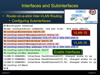
- 12. CCNA3-12 Chapter 6 • Router-on-a-stick Inter-VLAN Routing: • Configuring Subinterfaces: • Similar to configuring physical interfaces. • Create the subinterface. • Assign it to a VLAN. • Assign an IP Address. • Enable the interface. Interfaces and Subinterfaces
- 13. CCNA3-13 Chapter 6 • Router-on-a-stick Inter-VLAN Routing: • Create the subinterface: • The syntax for the subinterface is always the physical interface followed by a period and a subinterface number. • The subinterface number is configurable, but it is typically associated to reflect the VLAN number. R1(config)#interface [interface].nn NOTE: The management VLAN must also be configured if you wish to use it on multiple switches that are not directly connected by trunk links. Interfaces and Subinterfaces
- 14. CCNA3-14 Chapter 6 • Router-on-a-stick Inter-VLAN Routing: • Assign it to a VLAN: • Before assigning an IP Address, the interface must to be configured to operate on a specific VLAN using the proper encapsulation. R1(config-subif)#encapsulation dot1q vlan-id Interfaces and Subinterfaces
- 15. CCNA3-15 Chapter 6 • Router-on-a-stick Inter-VLAN Routing: • Assign an IP Address: • The IP Address assigned here will become the default gateway for that VLAN. R1(config-subif)#ip address [address] [mask] Interfaces and Subinterfaces
- 16. CCNA3-16 Chapter 6 • Router-on-a-stick Inter-VLAN Routing: • Enable the interface: • Subinterfaces are not enabled individually. • When the physical interface is enabled, all associated subinterfaces are enabled. R1(config-if)#no shutdown Interfaces and Subinterfaces
- 17. CCNA3-17 Chapter 6 • Router-on-a-stick Inter-VLAN Routing: • Configuring Subinterfaces: Interfaces and Subinterfaces VLAN 10VLAN 10VLAN 10VLAN 10VLAN 10VLAN 10VLAN 10VLAN 10 VLAN 30VLAN 30VLAN 30VLAN 30 VLAN 10VLAN 10VLAN 10VLAN 10 VLAN 30VLAN 30VLAN 30VLAN 30 Enable InterfacesEnable InterfacesEnable InterfacesEnable Interfaces
- 18. CCNA3-18 Chapter 6 • Router-on-a-stick Inter-VLAN Routing: • Configuring Subinterfaces: Interfaces and Subinterfaces Planning!Planning!Planning!Planning!
- 19. CCNA3-19 Chapter 6 • Router Interface and Subinterface Comparison: Interfaces and Subinterfaces
- 20. CCNA3-20 Chapter 6 • Layer 3 Switch Inter-VLAN Routing: • Uses Switch Virtual Interfaces (SVI) to retag the frame. Introducing Inter-VLAN Routing VLANVLAN TaggedTagged (10)(10) VLANVLAN TaggedTagged (10)(10) TagTag removedremoved TagTag removedremoved
- 21. CCNA3-21 Chapter 6 Inter-VLAN Routing Configuring Inter-VLAN RoutingConfiguring Inter-VLAN Routing (Putting It All Together)(Putting It All Together)
- 22. CCNA3-22 Chapter 6 • Traditional Inter-VLAN Routing: Configuring Inter-VLAN Routing
- 23. CCNA3-23 Chapter 6 • Traditional Inter-VLAN Routing: Configuring Inter-VLAN Routing
- 24. CCNA3-24 Chapter 6 • Traditional Inter-VLAN Routing: Configuring Inter-VLAN Routing
- 25. CCNA3-25 Chapter 6 • Router-on-a-stick Inter-VLAN Routing: Configuring Inter-VLAN Routing VLANsVLANsVLANsVLANs TrunkTrunkTrunkTrunk InterfacesInterfacesInterfacesInterfaces VLANsVLANsVLANsVLANs Trunk inTrunk in Native VLANNative VLAN Trunk inTrunk in Native VLANNative VLAN
- 26. CCNA3-26 Chapter 6 • Router-on-a-stick Inter-VLAN Routing: Configuring Inter-VLAN Routing VLAN 10VLAN 10VLAN 10VLAN 10 VLAN 30VLAN 30VLAN 30VLAN 30 Enable AllEnable All SubinterfacesSubinterfaces Enable AllEnable All SubinterfacesSubinterfaces