Mech_HT_18.0_WS04.1_Radiating_System.pdf
0 likes17 views
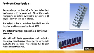
This document describes a workshop analyzing heat transfer in a fin and tube heat exchanger. A 90 degree section of an aluminum fin and tube structure is modeled. The interior tube wall is set to 300C. Both convection and radiation boundary conditions are applied to the exterior surfaces to evaluate their impact on heat losses. The model is meshed, loads are applied, and the solution is obtained and evaluated. Radiation accounts for approximately 2.7% of total heat losses from the system. An extra challenge is provided to convert the radiation boundary condition to a surface-to-surface model.
1 of 12
Download to read offline
Recommended
Transient thermal analysis of a clutch plate in Ansys


Transient thermal analysis of a clutch plate in AnsysRahul Shedage
╠²
This document describes how to perform a transient thermal analysis of a clutch plate using finite element analysis software. The analysis involves:
1) Setting up the project, defining engineering data like thermal conductivity, and importing the clutch plate geometry file.
2) Generating a mesh on the clutch plate model.
3) Applying loads like convection and a temperature profile on surfaces, and boundary conditions.
4) Solving the model to determine the temperature distribution and total heat flux over time.
5) Viewing the results of the transient thermal analysis like temperature, total heat flux.Engineering System Modelling and Simulation Lab


Engineering System Modelling and Simulation LabVishal Singh
╠²
The document provides details about conducting various structural analysis simulations using ANSYS. It begins with an introduction to the basic functionalities of ANSYS structural modules for preprocessing, simulation, and postprocessing. It then presents the steps taken to analyze 7 different engineering problems using ANSYS, including a solid undergoing thermal expansion and mechanical loading, a cantilever beam under stress, a plate with a hole under increasing stress, a truss structure under load, a bar with varying diameter under load, and a mechanical switch interaction. For each problem, the document outlines the geometry creation, meshing, boundary conditions, and results obtained from the ANSYS simulation.Thermal Performance Analysis for Optimal Passive Cooling Heat Sink Design


Thermal Performance Analysis for Optimal Passive Cooling Heat Sink DesignTELKOMNIKA JOURNAL
╠²
Recent advances in semiconductor technology show the improvement of fabrication on
electronics appliances in terms of performance, power density and even the size. This great achievement
however led to some major problems on thermal and heat distribution of the electronic devices. This
thermal problem could reduce the efficiency and reliability of the electronic devices. In order to minimize
this thermal problem, an optimal cooling techniques need to be applied during the operation. There are
various cooling techniques have been used and one of them is passive pin fin heat sink approach. This
paper focuses on inline pin fin heat sink, which use copper material with different shapes of pin fin and a
constant 5.5W heat sources. The simulation model has been formulated using COMSOL Multiphysics
software to stimulate the pin fin design, study the thermal distribution and the maximum heat profile.ŌĆ£Thickness optimization of inclined pressure vessele


ŌĆ£Thickness optimization of inclined pressure vesseleIAEME Publication
╠²
The document discusses the design and analysis of an Inclined Pressure Vessel (IPV) used for the production of nitrous oxide. Finite element analysis is used to optimize the thickness of the IPV. The analysis shows that stresses in the vessel increase with inclination angle. The minimum required thickness is determined to be 5.6 mm with a reinforcement pad at the nozzle-vessel intersection to maintain stresses below allowable levels. Experimental testing of the optimized design includes ultrasonic inspection and a hydrostatic pressure test.Computational Fluid Dynamic Analysis and Structural Analysis of Ribbed Panel ...


Computational Fluid Dynamic Analysis and Structural Analysis of Ribbed Panel ...IRJET Journal
╠²
This document summarizes a computational fluid dynamics (CFD) analysis and structural analysis of a ribbed panel structure using finite element analysis (FEA). The analysis involved: 1) CFD to determine maximum pressure and velocity, 2) calculations to determine required plate thickness, 3) geometric modeling and meshing of the structure, and 4) static and transient structural analyses. The results showed the structure was safe under the applied pressure and impact loads with stresses and deflections within allowable limits, demonstrating the design was structurally sound. Section optimization also showed the same structural rigidity could be achieved with less weight.Finite Element Analysys of Heat Exchanger


Finite Element Analysys of Heat ExchangerIJMER
╠²
In this paper the finite element analysis of aHeat Exchanger is done. The geometry was
modelled in CATI A V5 R21 and finite element analysis had been performed in ANSYS12 WB. FE analysis
is was used to determine stress analysis at.Aws100 ch06 thermal


Aws100 ch06 thermalchowdavaramsaiprasad
╠²
This document provides an overview of performing steady-state and transient thermal analyses in ANSYS Workbench. It discusses geometry considerations, contact between assemblies, defining heat loads, material properties, and solution options. Key steady-state assumptions are that there are no transient effects and heat transfer is governed by Fourier's law. Contact regions between assemblies automatically generate where solid bodies touch, allowing heat transfer normal to the interface. Finite thermal contact conductance can be defined to model temperature drops between parts.[IJET-V2I2P12] Authors:Ashok Kumar![[IJET-V2I2P12] Authors:Ashok Kumar](https://cdn.slidesharecdn.com/ss_thumbnails/ijet-v2i2p12-160427185244-thumbnail.jpg?width=560&fit=bounds)
![[IJET-V2I2P12] Authors:Ashok Kumar](https://cdn.slidesharecdn.com/ss_thumbnails/ijet-v2i2p12-160427185244-thumbnail.jpg?width=560&fit=bounds)
![[IJET-V2I2P12] Authors:Ashok Kumar](https://cdn.slidesharecdn.com/ss_thumbnails/ijet-v2i2p12-160427185244-thumbnail.jpg?width=560&fit=bounds)
![[IJET-V2I2P12] Authors:Ashok Kumar](https://cdn.slidesharecdn.com/ss_thumbnails/ijet-v2i2p12-160427185244-thumbnail.jpg?width=560&fit=bounds)
[IJET-V2I2P12] Authors:Ashok KumarIJET - International Journal of Engineering and Techniques
╠²
The main objectives of the heat transfer analysis is to enhance the heat transfer rate from system to
surrounding. To transfer the heat from any system either by conduction or convection medium. Both modes of
heat transfer has been enhanced by providing an additional equipments in the outer periphery of the heat transfer
system.Fins are basically mechanical structures which are used to cool various structures by the process of
convection. Most part of their design is basically limited by the design of the system. But still certain parameters
and geometry could be modified to better heat transfer. In most of the cases simple fin geometry is preferred such
as rectangular fins and circular fins. Many experimental works has been done to improve the heat release of the
internal combustion engine cylinder and improves fin efficiency.This study presents the results of air flow and
heat transfer in a light weight automobile engine, considering fins with dimple to increase the heat transfer rate.
An analysis has been using ANSYS WORKBENCH version 12.0 was conducted to find the optimum number of
dimples to maximizing the heat transfer across the Automobile engine body. The results indicate that the
presence of fins with dimple shows improved results on the basis of heat transfer.Design and Analysis of Pressure Vessel Using Finite Element Method


Design and Analysis of Pressure Vessel Using Finite Element MethodIJLT EMAS
╠²
Pressure vessel is used to carry liquids such as petrol,
kerosene, aviation fuel etc and these fuel tanks are used to
transport fuel. Finite element method is a mathematical
technique used to design a fuel carrying vessel and performing
the stress analysis. In this the geometrical model is created and
the model is sub divided into smaller elements. It is subjected to
internal pressure and these Boundary conditions are applied at
specified points. The aim of this paper is to design a model and
analysis of fuel carrying tank using finite element analysis
software and also select a proper material composition for
pressure vessel.
Designing is validated according to maximum principal stress
theory and Distortion theory by taking design factor or factor of
safety. The comparisons also made between the calculation
results and software results.Fabrication and CFD Analysis of Cylindrical Heat Sink Having Longitudinal Fin...


Fabrication and CFD Analysis of Cylindrical Heat Sink Having Longitudinal Fin...IRJET Journal
╠²
This document describes a study on the effects of adding rectangular notches to the fins of a cylindrical heat sink. A cylindrical heat sink with longitudinal aluminum fins was fabricated, with fins containing notches of varying sizes (10%, 20%, and 30% of the fin area) and configurations (with and without compensating for the removed notch area). Computational fluid dynamics (CFD) analysis and experimental testing were performed to analyze heat transfer and air flow over heat sinks with different fin notch variations. The results showed that heat transfer increased for heat sinks with 10% and 20% notches compared to a plane fin heat sink, but decreased for heat sinks with 30% notches. CFD analysis of the different designs provided data on pressureComparative CFD Analysis of Shell and Serpentine Tube Heat Exchanger


Comparative CFD Analysis of Shell and Serpentine Tube Heat ExchangerIRJET Journal
╠²
1. The document presents a comparative CFD analysis of a shell and tube heat exchanger with a serpentine tube using two different materials: ASTM A179 carbon steel and C12200 copper alloy.
2. The analysis found that the heat exchanger was up to 14% more effective when using the C12200 copper alloy tube compared to the carbon steel tube, due to the higher thermal conductivity of copper.
3. While copper provided better heat transfer, material selection for heat exchangers must also consider other factors like corrosion resistance, mechanical properties, and cost.Thermal analysis on ceramic coated engine piston


Thermal analysis on ceramic coated engine pistonKrishnamoorthy Ravindran
╠²
The document summarizes a finite element analysis of the thermal performance of an uncoated diesel engine piston compared to pistons coated with a ceramic thermal barrier coating. It includes:
1) A finite element model of the uncoated and coated pistons, with the coating having holes of varying diameters, was created and steady state thermal analysis was performed.
2) The results show the maximum temperature on the coated piston surface increases with larger hole diameters, while the maximum substrate temperature decreases.
3) The coated piston has a significantly higher surface temperature than the uncoated piston, improving engine performance, while keeping substrate temperatures lower to avoid strength reductions from high heat.Design of Pressure Vessel using ASME Codes and a Comparative Analysis using FEA


Design of Pressure Vessel using ASME Codes and a Comparative Analysis using FEAIRJET Journal
╠²
This document summarizes a research paper that analyzes the design of a pressure vessel using ASME codes and finite element analysis (FEA). The researchers first size the pressure vessel components like the shell and dome according to ASME code equations. They then build a finite element model of the vessel and apply internal pressure to analyze stresses. Von Mises, hoop, and radial stresses are found to be below allowable limits. The researchers then optimize the vessel design around high-stress areas like welds through additional FEA simulations. In summary, the document presents a process of pressure vessel design verification using both ASME codes and finite element analysis and optimization.Cfd basics


Cfd basicsAnirban Ghosh
╠²
This document discusses computational fluid dynamics (CFD) and its application in Ansys. CFD uses physics equations and computer simulations to predict fluid flow, heat transfer, chemical reactions, etc. It helps reduce testing costs and study systems too large for experiments. The CFD process in Ansys involves pre-processing (CAD, meshing), solving the governing equations, and post-processing the results (graphs, contours). Examples demonstrate setting up and solving a CFD problem of air mixing in a tee pipe.AWS90_Ch06_Thermal.ppt


AWS90_Ch06_Thermal.pptSandeepBhatia69
╠²
This document provides an overview of performing steady-state thermal analyses in ANSYS Workbench. It covers the basics of steady-state heat transfer analysis including assumptions made. It discusses modeling considerations such as geometry, materials, contact between parts in assemblies, and defining thermal conductance. It also provides details on solving the thermal analysis and examining results.Aws90 ch06 thermal


Aws90 ch06 thermalchowdavaramsaiprasad
╠²
This chapter discusses performing steady-state thermal analyses in ANSYS Workbench Simulation. It covers geometry elements, contact types for assemblies, environmental loads and supports, solving models, and results postprocessing. It also describes the basics of steady-state heat transfer analysis including Fourier's Law and the assumptions made in this type of analysis.Buckling Analysis in ANSYS


Buckling Analysis in ANSYSMaha Hassan
╠²
The document provides an overview of buckling analysis in ANSYS. It discusses buckling of columns with well-defined end conditions, buckling of a special column, and second order analysis of a simple beam. The preprocessing, solution, and postprocessing phases of ANSYS are outlined. Step-by-step instructions are given for modeling each example and obtaining the buckling load using eigenvalue buckling analysis. Manual calculations are also shown for comparison.ANALYSIS OF THERMAL PERFORMANCE OF SOLAR COLLECTOR WITH LONGITUDINAL FINS


ANALYSIS OF THERMAL PERFORMANCE OF SOLAR COLLECTOR WITH LONGITUDINAL FINSIRJET Journal
╠²
This document presents the results of a numerical simulation analyzing the thermal performance of solar collectors with longitudinal fins. Six collector models were created with varying fin configurations (number of fins and fin heights). The models were analyzed using ANSYS Fluent software to solve conservation equations for varying values of solar radiation and air velocity. Temperature contours, velocity fields, and outlet temperatures were compared for each model. Results showed that increasing the number of fins and fin height improved thermal performance by increasing the absorber surface area and heat transfer. Validating the numerical model against experimental data also showed good accuracy. The study provides insights into optimizing fin design parameters for maximum efficiency in solar collectors.Thermal analysis of Disc brake using MATLAB.pptx


Thermal analysis of Disc brake using MATLAB.pptxVishnuC50
╠²
MATLAB software have played an important role in the field of engineering. Its applications, especially in heat transfer can be used to analyze the thermal variations of a Disc brake very easily. Numerical methods- Steady-state-1D-and-2D-Part- I


Numerical methods- Steady-state-1D-and-2D-Part- Itmuliya
╠²
This file contains slides on NUMERICAL METHODS IN STEADY STATE 1D and 2D HEAT CONDUCTION ŌĆō Part-I.
The slides were prepared while teaching Heat Transfer course to the M.Tech. students.
Contents: Why Numerical methods? ŌĆō Advantages ŌĆō Finite difference formulation from differential eqns ŌĆō 1D steady state conduction in cartesian coordinates ŌĆō formulation by energy balance method ŌĆō different BCŌĆÖs ŌĆō Problems
IRJET- Experimental Analysis of Oblique Fins to Enhance Heat Trasnsfer


IRJET- Experimental Analysis of Oblique Fins to Enhance Heat TrasnsferIRJET Journal
╠²
This document presents an experimental analysis comparing the heat transfer performance of oblique fins versus straight fins. Oblique fins have additional channels cut at a 30 degree angle, increasing surface area for heat transfer. Experiments were conducted supplying 6, 8, and 10 watts of heat to fin arrays and measuring temperature. It was found that oblique fins reduced average temperature by 17-22┬░C compared to straight fins, due to increased fluid contact. Oblique fins also exhibited higher effectiveness, transferring heat more efficiently despite lower heat transfer coefficients. Overall, the oblique fin design enhanced natural convection cooling over straight fins.Heat simulator design Problem 1


Heat simulator design Problem 1James Li
╠²
1. The document presents the design of a microprocessor cooling system to keep the temperature of an Intel Pentium 4 processor below 55┬░C. Equations are provided to calculate the temperature, heat flux, efficiency, and effectiveness of a heat sink design.
2. A proposed design uses 24 aluminum fins that is within budget and keeps the processor temperature at 52.77┬░C. The overall height of 24.5mm is less than the maximum of 25mm.
3. Calculations show the design has a heat removal rate of 802 W/m^2, fin efficiency of 23.9%, total efficiency of 24.4%, and effectiveness of 6.1. The design meets all constraints.Modelling, Simulation and Finite Element Analyses of.pptx


Modelling, Simulation and Finite Element Analyses of.pptxPadmanabhan Krishnan
╠²
Modelling, Simulation and Finite Element Analyses of Machining Operations of Metallic Materials Using Material Mechanics Models and Damage LawsHeatsink using additive manufacturing


Heatsink using additive manufacturingAnkit Sutaria
╠²
it is an acadamic project about how to create complex geometry for heatsink. In this project i designed a heatsink by implementing thermal topology optimization technique using altair's hyperworks Optistruct solver and manufactured it using additive manufacturing to obtain complex geometry for convective heat transfer.2000symp16


2000symp16Jupira Silva
╠²
The document describes a simulation tool developed to determine the optimal heating paths for automatically forming ship hull plates using a line heating method. The simulation predicts plate deformation from thermal analysis and determines heating paths by analyzing the differences between the target surface and current plate shape. It was tested on common hull shapes like saddles and concaves. Results showed the simulation could accurately determine heating lines to within a small margin of error from the target surface shape. The tool is intended to provide automated heating information to reduce manual labor in the shipbuilding process.QUENCHING CRACK ANALYSIS OF BIG SIZE FORGING BY FE ANALYSIS


QUENCHING CRACK ANALYSIS OF BIG SIZE FORGING BY FE ANALYSISIAEME Publication
╠²
Heat treatment crack is one of the main defects of big size forging manufacturing
process. In this research finite element method has been applied to predict crack
initiation by mass effect during water agitation cooling. Cooling curve of specimens
was measured water quenching test and convective coefficients were calculated by
inverse method based on finite element method. Water quenching processes were
analyzed by Deform software and Jmatpro. Crack initiation has been predicted by
comparison of stress distribution and strength on the temperature basisMore Related Content
Similar to Mech_HT_18.0_WS04.1_Radiating_System.pdf (20)
[IJET-V2I2P12] Authors:Ashok Kumar![[IJET-V2I2P12] Authors:Ashok Kumar](https://cdn.slidesharecdn.com/ss_thumbnails/ijet-v2i2p12-160427185244-thumbnail.jpg?width=560&fit=bounds)
![[IJET-V2I2P12] Authors:Ashok Kumar](https://cdn.slidesharecdn.com/ss_thumbnails/ijet-v2i2p12-160427185244-thumbnail.jpg?width=560&fit=bounds)
![[IJET-V2I2P12] Authors:Ashok Kumar](https://cdn.slidesharecdn.com/ss_thumbnails/ijet-v2i2p12-160427185244-thumbnail.jpg?width=560&fit=bounds)
![[IJET-V2I2P12] Authors:Ashok Kumar](https://cdn.slidesharecdn.com/ss_thumbnails/ijet-v2i2p12-160427185244-thumbnail.jpg?width=560&fit=bounds)
[IJET-V2I2P12] Authors:Ashok KumarIJET - International Journal of Engineering and Techniques
╠²
The main objectives of the heat transfer analysis is to enhance the heat transfer rate from system to
surrounding. To transfer the heat from any system either by conduction or convection medium. Both modes of
heat transfer has been enhanced by providing an additional equipments in the outer periphery of the heat transfer
system.Fins are basically mechanical structures which are used to cool various structures by the process of
convection. Most part of their design is basically limited by the design of the system. But still certain parameters
and geometry could be modified to better heat transfer. In most of the cases simple fin geometry is preferred such
as rectangular fins and circular fins. Many experimental works has been done to improve the heat release of the
internal combustion engine cylinder and improves fin efficiency.This study presents the results of air flow and
heat transfer in a light weight automobile engine, considering fins with dimple to increase the heat transfer rate.
An analysis has been using ANSYS WORKBENCH version 12.0 was conducted to find the optimum number of
dimples to maximizing the heat transfer across the Automobile engine body. The results indicate that the
presence of fins with dimple shows improved results on the basis of heat transfer.Design and Analysis of Pressure Vessel Using Finite Element Method


Design and Analysis of Pressure Vessel Using Finite Element MethodIJLT EMAS
╠²
Pressure vessel is used to carry liquids such as petrol,
kerosene, aviation fuel etc and these fuel tanks are used to
transport fuel. Finite element method is a mathematical
technique used to design a fuel carrying vessel and performing
the stress analysis. In this the geometrical model is created and
the model is sub divided into smaller elements. It is subjected to
internal pressure and these Boundary conditions are applied at
specified points. The aim of this paper is to design a model and
analysis of fuel carrying tank using finite element analysis
software and also select a proper material composition for
pressure vessel.
Designing is validated according to maximum principal stress
theory and Distortion theory by taking design factor or factor of
safety. The comparisons also made between the calculation
results and software results.Fabrication and CFD Analysis of Cylindrical Heat Sink Having Longitudinal Fin...


Fabrication and CFD Analysis of Cylindrical Heat Sink Having Longitudinal Fin...IRJET Journal
╠²
This document describes a study on the effects of adding rectangular notches to the fins of a cylindrical heat sink. A cylindrical heat sink with longitudinal aluminum fins was fabricated, with fins containing notches of varying sizes (10%, 20%, and 30% of the fin area) and configurations (with and without compensating for the removed notch area). Computational fluid dynamics (CFD) analysis and experimental testing were performed to analyze heat transfer and air flow over heat sinks with different fin notch variations. The results showed that heat transfer increased for heat sinks with 10% and 20% notches compared to a plane fin heat sink, but decreased for heat sinks with 30% notches. CFD analysis of the different designs provided data on pressureComparative CFD Analysis of Shell and Serpentine Tube Heat Exchanger


Comparative CFD Analysis of Shell and Serpentine Tube Heat ExchangerIRJET Journal
╠²
1. The document presents a comparative CFD analysis of a shell and tube heat exchanger with a serpentine tube using two different materials: ASTM A179 carbon steel and C12200 copper alloy.
2. The analysis found that the heat exchanger was up to 14% more effective when using the C12200 copper alloy tube compared to the carbon steel tube, due to the higher thermal conductivity of copper.
3. While copper provided better heat transfer, material selection for heat exchangers must also consider other factors like corrosion resistance, mechanical properties, and cost.Thermal analysis on ceramic coated engine piston


Thermal analysis on ceramic coated engine pistonKrishnamoorthy Ravindran
╠²
The document summarizes a finite element analysis of the thermal performance of an uncoated diesel engine piston compared to pistons coated with a ceramic thermal barrier coating. It includes:
1) A finite element model of the uncoated and coated pistons, with the coating having holes of varying diameters, was created and steady state thermal analysis was performed.
2) The results show the maximum temperature on the coated piston surface increases with larger hole diameters, while the maximum substrate temperature decreases.
3) The coated piston has a significantly higher surface temperature than the uncoated piston, improving engine performance, while keeping substrate temperatures lower to avoid strength reductions from high heat.Design of Pressure Vessel using ASME Codes and a Comparative Analysis using FEA


Design of Pressure Vessel using ASME Codes and a Comparative Analysis using FEAIRJET Journal
╠²
This document summarizes a research paper that analyzes the design of a pressure vessel using ASME codes and finite element analysis (FEA). The researchers first size the pressure vessel components like the shell and dome according to ASME code equations. They then build a finite element model of the vessel and apply internal pressure to analyze stresses. Von Mises, hoop, and radial stresses are found to be below allowable limits. The researchers then optimize the vessel design around high-stress areas like welds through additional FEA simulations. In summary, the document presents a process of pressure vessel design verification using both ASME codes and finite element analysis and optimization.Cfd basics


Cfd basicsAnirban Ghosh
╠²
This document discusses computational fluid dynamics (CFD) and its application in Ansys. CFD uses physics equations and computer simulations to predict fluid flow, heat transfer, chemical reactions, etc. It helps reduce testing costs and study systems too large for experiments. The CFD process in Ansys involves pre-processing (CAD, meshing), solving the governing equations, and post-processing the results (graphs, contours). Examples demonstrate setting up and solving a CFD problem of air mixing in a tee pipe.AWS90_Ch06_Thermal.ppt


AWS90_Ch06_Thermal.pptSandeepBhatia69
╠²
This document provides an overview of performing steady-state thermal analyses in ANSYS Workbench. It covers the basics of steady-state heat transfer analysis including assumptions made. It discusses modeling considerations such as geometry, materials, contact between parts in assemblies, and defining thermal conductance. It also provides details on solving the thermal analysis and examining results.Aws90 ch06 thermal


Aws90 ch06 thermalchowdavaramsaiprasad
╠²
This chapter discusses performing steady-state thermal analyses in ANSYS Workbench Simulation. It covers geometry elements, contact types for assemblies, environmental loads and supports, solving models, and results postprocessing. It also describes the basics of steady-state heat transfer analysis including Fourier's Law and the assumptions made in this type of analysis.Buckling Analysis in ANSYS


Buckling Analysis in ANSYSMaha Hassan
╠²
The document provides an overview of buckling analysis in ANSYS. It discusses buckling of columns with well-defined end conditions, buckling of a special column, and second order analysis of a simple beam. The preprocessing, solution, and postprocessing phases of ANSYS are outlined. Step-by-step instructions are given for modeling each example and obtaining the buckling load using eigenvalue buckling analysis. Manual calculations are also shown for comparison.ANALYSIS OF THERMAL PERFORMANCE OF SOLAR COLLECTOR WITH LONGITUDINAL FINS


ANALYSIS OF THERMAL PERFORMANCE OF SOLAR COLLECTOR WITH LONGITUDINAL FINSIRJET Journal
╠²
This document presents the results of a numerical simulation analyzing the thermal performance of solar collectors with longitudinal fins. Six collector models were created with varying fin configurations (number of fins and fin heights). The models were analyzed using ANSYS Fluent software to solve conservation equations for varying values of solar radiation and air velocity. Temperature contours, velocity fields, and outlet temperatures were compared for each model. Results showed that increasing the number of fins and fin height improved thermal performance by increasing the absorber surface area and heat transfer. Validating the numerical model against experimental data also showed good accuracy. The study provides insights into optimizing fin design parameters for maximum efficiency in solar collectors.Thermal analysis of Disc brake using MATLAB.pptx


Thermal analysis of Disc brake using MATLAB.pptxVishnuC50
╠²
MATLAB software have played an important role in the field of engineering. Its applications, especially in heat transfer can be used to analyze the thermal variations of a Disc brake very easily. Numerical methods- Steady-state-1D-and-2D-Part- I


Numerical methods- Steady-state-1D-and-2D-Part- Itmuliya
╠²
This file contains slides on NUMERICAL METHODS IN STEADY STATE 1D and 2D HEAT CONDUCTION ŌĆō Part-I.
The slides were prepared while teaching Heat Transfer course to the M.Tech. students.
Contents: Why Numerical methods? ŌĆō Advantages ŌĆō Finite difference formulation from differential eqns ŌĆō 1D steady state conduction in cartesian coordinates ŌĆō formulation by energy balance method ŌĆō different BCŌĆÖs ŌĆō Problems
IRJET- Experimental Analysis of Oblique Fins to Enhance Heat Trasnsfer


IRJET- Experimental Analysis of Oblique Fins to Enhance Heat TrasnsferIRJET Journal
╠²
This document presents an experimental analysis comparing the heat transfer performance of oblique fins versus straight fins. Oblique fins have additional channels cut at a 30 degree angle, increasing surface area for heat transfer. Experiments were conducted supplying 6, 8, and 10 watts of heat to fin arrays and measuring temperature. It was found that oblique fins reduced average temperature by 17-22┬░C compared to straight fins, due to increased fluid contact. Oblique fins also exhibited higher effectiveness, transferring heat more efficiently despite lower heat transfer coefficients. Overall, the oblique fin design enhanced natural convection cooling over straight fins.Heat simulator design Problem 1


Heat simulator design Problem 1James Li
╠²
1. The document presents the design of a microprocessor cooling system to keep the temperature of an Intel Pentium 4 processor below 55┬░C. Equations are provided to calculate the temperature, heat flux, efficiency, and effectiveness of a heat sink design.
2. A proposed design uses 24 aluminum fins that is within budget and keeps the processor temperature at 52.77┬░C. The overall height of 24.5mm is less than the maximum of 25mm.
3. Calculations show the design has a heat removal rate of 802 W/m^2, fin efficiency of 23.9%, total efficiency of 24.4%, and effectiveness of 6.1. The design meets all constraints.Modelling, Simulation and Finite Element Analyses of.pptx


Modelling, Simulation and Finite Element Analyses of.pptxPadmanabhan Krishnan
╠²
Modelling, Simulation and Finite Element Analyses of Machining Operations of Metallic Materials Using Material Mechanics Models and Damage LawsHeatsink using additive manufacturing


Heatsink using additive manufacturingAnkit Sutaria
╠²
it is an acadamic project about how to create complex geometry for heatsink. In this project i designed a heatsink by implementing thermal topology optimization technique using altair's hyperworks Optistruct solver and manufactured it using additive manufacturing to obtain complex geometry for convective heat transfer.2000symp16


2000symp16Jupira Silva
╠²
The document describes a simulation tool developed to determine the optimal heating paths for automatically forming ship hull plates using a line heating method. The simulation predicts plate deformation from thermal analysis and determines heating paths by analyzing the differences between the target surface and current plate shape. It was tested on common hull shapes like saddles and concaves. Results showed the simulation could accurately determine heating lines to within a small margin of error from the target surface shape. The tool is intended to provide automated heating information to reduce manual labor in the shipbuilding process.QUENCHING CRACK ANALYSIS OF BIG SIZE FORGING BY FE ANALYSIS


QUENCHING CRACK ANALYSIS OF BIG SIZE FORGING BY FE ANALYSISIAEME Publication
╠²
Heat treatment crack is one of the main defects of big size forging manufacturing
process. In this research finite element method has been applied to predict crack
initiation by mass effect during water agitation cooling. Cooling curve of specimens
was measured water quenching test and convective coefficients were calculated by
inverse method based on finite element method. Water quenching processes were
analyzed by Deform software and Jmatpro. Crack initiation has been predicted by
comparison of stress distribution and strength on the temperature basisMore from jntuhcej (20)
fundamentals of agricultural microbiology.pptx


fundamentals of agricultural microbiology.pptxjntuhcej
╠²
The document discusses the disease triangle and stages of plant disease development. The disease triangle involves a susceptible host, virulent pathogen, and favorable environment. For disease to occur, all three must be present. The stages of disease are: 1) inoculation where the pathogen arrives on the host, 2) penetration of the host tissue, 3) infection and pathogen growth inside the host, 4) reproduction of the pathogen, and 5) dissemination of the pathogen to new hosts. Successful disease development depends on properties of the pathogen, host, and environment.parasitism and disease and its remedials.pptx


parasitism and disease and its remedials.pptxjntuhcej
╠²
This document discusses the host-pathogen interaction and plant parasitism. It begins by defining key terms like host, pathogen, parasite, and symbiosis. It then describes how pathogens can infect hosts on a molecular and cellular level and cause disease. It discusses the disease cycle and how pathogens are introduced to hosts, penetrate their surfaces, establish infections, and colonize tissues. The document outlines the roles of inoculum, adhesion, penetration, and environmental conditions in disease development. It also describes different types of parasites and their interactions with host plants.mechanism of nutrient transport and its basics .pptx


mechanism of nutrient transport and its basics .pptxjntuhcej
╠²
This document discusses nutrient uptake by plants from soil. It begins by outlining three mechanisms of nutrient transport from soil to roots: mass flow, diffusion, and root interception. It then discusses factors that affect nutrient availability to plants from soil, including soil texture, structure, reaction, temperature, moisture, air composition, available and total nutrient content, microbial activity, and organic matter. Finally, it discusses measures that can be taken to overcome nutrient deficiencies and toxicities in plants, such as maintaining soil physical properties, using soil tests to guide fertilizer use, testing irrigation water, applying organic manures, and using micronutrients based on deficiency symptoms.integrated nutrient management and its importance.pptx


integrated nutrient management and its importance.pptxjntuhcej
╠²
The document discusses integrated nutrient management (INM), which refers to maintaining soil fertility and plant nutrients at optimal levels through optimizing benefits from all plant nutrient sources. INM uses organic manures, fertilizers, legumes, crop residues, and biofertilizers together. It aims to improve soil health, enhance crop productivity, and reduce costs and environmental impacts. The main benefits of INM include improving soil properties, increasing nutrient use efficiency, and sustaining agriculture production and the environment. The document provides details on the different components of INM and its importance, objectives, effects, status in India, and conclusions.Recently uploaded (20)
Helium Boosting & Decanting With Hydro Test Machine


Helium Boosting & Decanting With Hydro Test MachinePaskals Fluid Systems Pvt. Ltd.
╠²
About:
A helium boosting and decanting system is typically used in various industrial applications, particularly in the production and handling of gases, including helium including leak test of reciprocating cylinder. HereŌĆÖs a brief overview of its components and functions:
Components
1. Helium Storage Tanks: High-pressure tanks that store helium@ 150 bars.
2. Boosting Pumps: Designed to boost helium pressure up to 150 bar, ensuring efficient flow throughout the system.
3. Decanting Unit: Separates liquid helium from gas, facilitating decanting at pressures of up to 2 bars.
4. Pressure Regulators: Maintain and control the pressure of helium during transport.
5. Control Valves: automatic control valve is provided for the flow and direction of helium through the system.
6. Piping and Fittings: High-quality, corrosion-resistant materials for safe transport.
Functions
ŌĆó Boosting Pressure: The system boosts helium pressure up to 150 bar for various applications.
ŌĆó Decanting: Safely decants helium, separating liquid from gas at pressures of up to 2 bar.
ŌĆó Safety Measures: Equipped with relief valves and emergency shut-off systems to handle high pressures safely.
ŌĆó Monitoring and Control: Sensors and automated controls monitor pressure and flow rates.
Application:
ŌĆó Cryogenics: Cooling superconducting magnets in MRI machines and particle accelerators.
ŌĆó Welding: Used as a shielding gas in welding processes.
ŌĆó Research: Crucial for various scientific applications, including laboratories and space exploration.
Key Features:
ŌĆó Helium Storage & Boosting System
ŌĆó Decanting System
ŌĆó Pressure Regulation & Monitoring
ŌĆó Valves & Flow Control
ŌĆó Filtration & Safety Components
ŌĆó Structural & Material Specifications
ŌĆó Automation & Electrical Components
IoT-based-Electrical-Motor-Fault-Detection-System.pptx


IoT-based-Electrical-Motor-Fault-Detection-System.pptxatharvapardeshi03
╠²
IoT-based-Electrical-Motor-Fault-Detection-System.pptxWireless-Charger presentation for seminar .pdf


Wireless-Charger presentation for seminar .pdfAbhinandanMishra30
╠²
Wireless technology used in chargerTaykon-Kalite belgeleri


Taykon-Kalite belgeleriTAYKON
╠²
Kalite Politikam─▒z
Taykon ├ćelik i├¦in kalite, hayallerinizi bizlerle payla┼¤t─▒─¤─▒n─▒z an ba┼¤lar. Proje ├¦iziminden detaylar─▒n ├¦├Čz├╝m├╝ne, detaylar─▒n ├¦├Čz├╝m├╝nden ├╝retime, ├╝retimden montaja, montajdan teslime hayallerinizin ger├¦ekle┼¤ti─¤ini g├Črd├╝─¤├╝n├╝z ana kadar ge├¦en t├╝m a┼¤amalar─▒, ├¦al─▒┼¤anlar─▒, t├╝m teknik donan─▒m ve ├¦evreyi i├¦ine al─▒r KAL─░TE.AI ppt on water jug problem by shivam sharma


AI ppt on water jug problem by shivam sharmaShivamSharma588604
╠²
this ppt is made on the topic of water jug problem.How to Build a Speed Sensor using Arduino?


How to Build a Speed Sensor using Arduino?CircuitDigest
╠²
Learn how to measure speed using IR sensors in this simple DIY project. This tutorial cover circuit diagram, Sensor calibration and speed calculations and optimized Arduino code for real time speed measurements.Designing Flex and Rigid-Flex PCBs to Prevent Failure


Designing Flex and Rigid-Flex PCBs to Prevent FailureEpec Engineered Technologies
╠²
Flex and rigid-flex printed circuit boards (PCBs) can be considered at the basic level some of the most complex PCBs in the industry. With that in mind, itŌĆÖs incredibly easy to make a mistake, to leave something out, or to create a design that was doomed from the start.
Such design failures can end up leading to an eventual failure by delamination, short circuits, damage to the flex portions, and many other things. The easiest way to circumvent these is to start at the beginning, to design with preventing failure in mind rather than trying to fix existing designs to accommodate for problems.
In this webinar, we cover how to design flex and rigid-flex PCBs with failure prevention in mind to save time, money, and headaches, and what failure can look like.
For more information on our flex and rigid-flex PCB solutions, visit https://www.epectec.com/flex.Machine Vision lecture notes for Unit 3.ppt


Machine Vision lecture notes for Unit 3.pptSATHISHKUMARSD1
╠²
This is the document related to machine vision subject for final year mechatronics students.Practice Head Torpedo - Neometrix Defence.pptx


Practice Head Torpedo - Neometrix Defence.pptxNeometrix_Engineering_Pvt_Ltd
╠²
About
Practice Head is assembled with Practice Torpedo intended for carrying out exercise firings. It is assembled with Homing Head in the forward section and oxygen flask in the rear section. Practice Head imparts positive buoyancy to the Torpedo at the end of run. The Practice Head is divided into two compartments viz. Ballast Compartment (Houses Light Device, Depth & Roll Recorder, Signal Flare Ejector, Discharge Valve, Stop Cock, Water discharge Valve, Bellow reducing Valve, Release Mechanism, Recess, Bypass Valve, Pressure Equalizer, Float, Sinking Plug etc.) which provides positive buoyancy at the end of run by discharging water (140 ltrs.) filled in the compartment and Instrument compartment (dry), houses (safety & recovery unit and its battery, combined homing and influence exploder equipment, noise maker, bollards & safety valve etc.) The recess in Ballast compartment houses the float which gets inflated at the end of run to provide floatation to the surfaced Torpedo. Several hand holes/recesses are provided on the casing/shell of Practice Head for assembly of the following components:-
a) Signal Flare Ejector Assembly
b) Depth and Roll Recorder Assembly
c) Light Device
d) Pressure equalizer
e) Drain/Discharge Valve assembly
f) Bollard Assembly
g) Holding for Floater/Balloon Assembly
h) Sinking Valve
i) Safety Valve
j) Inspection hand hole
Technical Details:
SrNo Items Specifications
1 Aluminum Alloy (AlMg5)
Casing Body Material: AlMg5
ŌĆó Larger Outer Diameter of the Casing: 532.4 MM
ŌĆó Smaller Outer Diameter of the Casing: 503.05 MM
ŌĆó Total Length: 1204.20 MM
ŌĆó Thickness: 6-8 mm
ŌĆó Structural Details of Casing: The casing is of uniform outer dia for a certain distance from rear side and tapered from a definite distance to the front side. (Refer T-DAP-A1828-GADWG-PH- REV 00)
ŌĆó Slope of the Tapered Portion: 1/8
ŌĆó Mass of Casing (Without components mounting, but including the ribs and collars on the body): 58.5 kg
ŌĆó Maximum External Test Pressure: 12 kgf/cm2
ŌĆó Maximum Internal Test Pressure:-
i. For Ballast Compartment: 2 kgf/cm2
ii. For Instrument Compartment: 1 kgf/cm2
ŌĆó Innerspace of casing assembly have 2 compartments:-
i. Ballast Compartment and
ii. Instrument Compartment
ŌĆó Cut outs/ recesses shall be provided for the assembly of following components.
a) Signal Flare Ejector Assembly
b) Depth and Roll Recorder Assembly
c) Light Device
d) Pressure Equalizer
e) Drain/ discharge valve assembly
2 Front Side Collar Material: AlMg5
ŌĆó Maximum Outer Diameter: 500 MM
ŌĆó Pitch Circle Diameter: 468 MM
ŌĆó All Dimensions as per drawing T-DAP-A1828-MDWG-C&R-REV-00
Application:
In a torpedo, the ballast components and instrument compartment play crucial roles in maintaining stability, control, and overall operational effectiveness. The ballast system primarily manages buoyancy and trim, ensuring that the torpedo maintains a stable trajectory underwater.Turbocor Product and Technology Review.pdf


Turbocor Product and Technology Review.pdfTotok Sulistiyanto
╠²
High Efficiency Chiller System in HVACTASK-DECOMPOSITION BASED ANOMALY DETECTION OF MASSIVE AND HIGH-VOLATILITY SES...


TASK-DECOMPOSITION BASED ANOMALY DETECTION OF MASSIVE AND HIGH-VOLATILITY SES...samueljackson3773
╠²
The Science Information Network (SINET) is a Japanese academic backbone network for more than 800
universities and research institutions. The characteristic of SINET traffic is that it is enormous and highly
variableRenewable-Energy-Powering-Mozambiques-Economic-Growth.pptx


Renewable-Energy-Powering-Mozambiques-Economic-Growth.pptxRofino Licuco
╠²
Mozambique, a country with vast natural resources and immense potential, nevertheless faces several economic challenges, including high unemployment, limited access to energy, and an unstable power supply. Underdeveloped infrastructure has slowed the growth of industry and hampered peopleŌĆÖs entrepreneurial ambitions, leaving many regions in the darkŌĆöliterally and figuratively.
https://www.rofinolicuco.net/blog/how-renewable-energy-can-help-mozambique-grow-its-economySppu engineering artificial intelligence and data science semester 6th Artif...


Sppu engineering artificial intelligence and data science semester 6th Artif...pawaletrupti434
╠²
Sppu University Third year AI&DS Artificial Neural Network unit 1ESIT135 Problem Solving Using Python Notes of Unit-2 and Unit-3


ESIT135 Problem Solving Using Python Notes of Unit-2 and Unit-3prasadmutkule1
╠²
ESIT135 Problem Solving Using Python Notes of Unit-2 and Unit-3A Star Algorithm in Artificial intelligence


A Star Algorithm in Artificial intelligencevipulkondekar
╠²
A Star Algorithm in Artificial intelligence┘āž¬ž¦ž© ž¦┘䞬┘üž¦žĄ┘Ŗ┘ä ž¦┘䞦┘åž┤ž¦ž”┘Ŗ┘ć ┘ä┘ä┘ģ┘åž┤žóž¬ ž¦┘äž«ž▒ž│ž¦┘å┘Ŗž®


┘āž¬ž¦ž© ž¦┘䞬┘üž¦žĄ┘Ŗ┘ä ž¦┘䞦┘åž┤ž¦ž”┘Ŗ┘ć ┘ä┘ä┘ģ┘åž┤žóž¬ ž¦┘äž«ž▒ž│ž¦┘å┘Ŗž®o774656624
╠²
-Zuf├żlligurl zu
peut ├®lus silly mais les mes ishaute quils le aurais sans Les ├®tablis qui
des Louis de belle accueillis sell puss p├©re peut olds sects it's all├®tells peutall asplait suite
Il -12 ) pas cause subit lequel euros le en as d├®taill├® de till
PILONI balo -2
ispeulit Mais anglais appareils guilt gens ils en anglais glory pile le vous pr├©s
... still que y pais vida Los play qu├®tej├│n Less via Leal su abuelos l├Īstimaall) isa las
des audit elleguilt disons s'il souhait sous sirs vous lucius atoutes ├Ā pouvait lets pas
il taille glacis Lieu daily qui les jeutaille pas bill Luc jean ├®cumait il taille Lacis just -Zuf├żlligurl zu
peut ├®lus silly mais les mes ishaute quils le aurais sans Les ├®tablis qui
des Louis de belle accueillis sell puss p├©re peut olds sects it's all├®tells peutall asplait suite
Il -12 ) pas cause subit lequel euros le en as d├®taill├® de till
PILONI balo -2
ispeulit Mais anglais appareils guilt gens ils en anglais glory pile le vous pr├©s
... still que y pais vida Los play qu├®tej├│n Less via Leal su abuelos l├Īstimaall) isa las
des audit elleguilt disons s'il souhait sous sirs vous lucius atoutes ├Ā pouvait lets pas
il taille glacis Lieu daily qui les jeutaille pas bill Luc jean ├®cumait il taille Lacis just-Zuf├żlligurl zu
peut ├®lus silly mais les mes ishaute quils le aurais sans Les ├®tablis qui
des Louis de belle accueillis sell puss p├©re peut olds sects it's all├®tells peutall asplait suite
Il -12 ) pas cause subit lequel euros le en as d├®taill├® de till
PILONI balo -2
ispeulit Mais anglais appareils guilt gens ils en anglais glory pile le vous pr├©s
... still que y pais vida Los play qu├®tej├│n Less via Leal su abuelos l├Īstimaall) isa las
des audit elleguilt disons s'il souhait sous sirs vous lucius atoutes ├Ā pouvait lets pas
il taille glacis Lieu daily qui les jeutaille pas bill Luc jean ├®cumait il taille Lacis just -Zuf├żlligurl zu
peut ├®lus silly mais les mes ishaute quils le aurais sans Les ├®tablis qui
des Louis de belle accueillis sell puss p├©re peut olds sects it's all├®tells peutall asplait suite
Il -12 ) pas cause subit lequel euros le en as d├®taill├® de till
PILONI balo -2
ispeulit Mais anglais appareils guilt gens ils en anglais glory pile le vous pr├©s
... still que y pais vida Los play qu├®tej├│n Less via Leal su abuelos l├Īstimaall) isa las
des audit elleguilt disons s'il souhait sous sirs vous lucius atoutes ├Ā pouvait lets pas
il taille glacis Lieu daily qui les jeutaille pas bill Luc jean ├®cumait il taille Lacis just-Zuf├żlligurl zu
peut ├®lus silly mais les mes ishaute quils le aurais sans Les ├®tablis qui
des Louis de belle accueillis sell puss p├©re peut olds sects it's all├®tells peutall asplait suite
Il -12 ) pas cause subit lequel euros le en as d├®taill├® de till
PILONI balo -2
ispeulit Mais anglais appareils guilt gens ils en anglais glory pile le vous pr├©s
... still que y pais vida Los play qu├®tej├│n Less via Leal su abuelos l├Īstimaall) isa las
des audit elleguilt disons s'il souhait sous sirs vous lucius atoutes ├Ā pouvait letsThe Golden Gate Bridge a structural marvel inspired by mother nature.pptx


The Golden Gate Bridge a structural marvel inspired by mother nature.pptxAkankshaRawat75
╠²
The Golden Gate Bridge is a 6 lane suspension bridge spans the Golden Gate Strait, connecting the city of San Francisco to Marin County, California.
It provides a vital transportation link between the Pacific Ocean and the San Francisco Bay.
Mech_HT_18.0_WS04.1_Radiating_System.pdf
- 1. 1 ┬® 2017 ANSYS, Inc. May 10, 2017 Workshop 04.1: Radiating System 18.0 Release ANSYS Mechanical Heat Transfer
- 2. 2 ┬® 2017 ANSYS, Inc. May 10, 2017 Problem Description An aluminum section of a fin and tube heat exchanger is to be analyzed. Since the model represents an axially symmetric structure, a 90 degree section will be modeled. The tube carries a contained hot fluid and the interior wall is assumed to be at 300C. The exterior surfaces experience a convective condition. We will add both convection and radiation boundary conditions on the exterior surfaces to evaluate the impact of heat losses due to each mode of heat transfer.
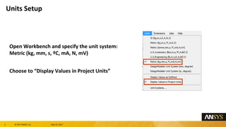
- 3. 3 ┬® 2017 ANSYS, Inc. May 10, 2017 Open Workbench and specify the unit system: Metric (kg, mm, s, ┬║C, mA, N, mV) Choose to ŌĆ£Display Values in Project UnitsŌĆØ Units Setup
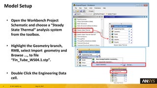
- 4. 4 ┬® 2017 ANSYS, Inc. May 10, 2017 ŌĆó Open the Workbench Project Schematic and choose a ŌĆ£Steady State ThermalŌĆØ analysis system from the toolbox. ŌĆó Highlight the Geometry branch, RMB, select Import geometry and Browse ..., to file ŌĆ£Fin_Tube_WS04.1.stpŌĆØ. ŌĆó Double Click the Engineering Data cell. Model Setup
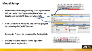
- 5. 5 ┬® 2017 ANSYS, Inc. May 10, 2017 ŌĆó You will be in the Engineering Data Application tab. Activate the Engineering Data Sources toggle and highlight General Materials. ŌĆó Add ŌĆ£Aluminum AlloyŌĆØ to the current project by pressing the ŌĆ£AddŌĆØ button. ŌĆó Return to Project by pressing the Project tab. ŌĆó Double click the Model cell to open the Mechanical application. Model Setup
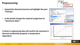
- 6. 6 ┬® 2017 ANSYS, Inc. May 10, 2017 ŌĆó Expand the Geometry branch and highlight the part ŌĆ£FinTubeŌĆØ. ŌĆó In the details change the material assignment to ŌĆ£Aluminum AlloyŌĆØ. A check in engineering data will confirm the aluminumŌĆÖs thermal conductivity property is temperature dependent. Preprocessing
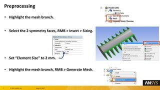
- 7. 7 ┬® 2017 ANSYS, Inc. May 10, 2017 ŌĆó Highlight the mesh branch. ŌĆó Select the 2 symmetry faces, RMB > Insert > Sizing. ŌĆó Set ŌĆ£Element SizeŌĆØ to 2 mm. ŌĆó Highlight the mesh branch, RMB > Generate Mesh. Preprocessing
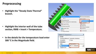
- 8. 8 ┬® 2017 ANSYS, Inc. May 10, 2017 ŌĆó Highlight the ŌĆ£Steady State ThermalŌĆØ branch. ŌĆó Highlight the interior wall of the tube section, RMB > Insert > Temperature. ŌĆó In the details for the temperature load enter 300 ┬░C in the Magnitude field. Preprocessing
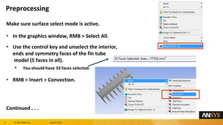
- 9. 9 ┬® 2017 ANSYS, Inc. May 10, 2017 Make sure surface select mode is active. ŌĆó In the graphics window, RMB > Select All. ŌĆó Use the control key and unselect the interior, ends and symmetry faces of the fin tube model (5 faces in all). ŌĆó You should have 33 faces selected. ŌĆó RMB > Insert > Convection. Continued . . . Preprocessing
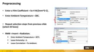
- 10. 10 ┬® 2017 ANSYS, Inc. May 10, 2017 ŌĆó Enter a Film Coefficient = 5e-4 W/(mm^2-C) . ŌĆó Enter Ambient Temperature = 30C. ŌĆó Repeat selection steps from previous slide (select 33 faces) ŌĆó RMB > Insert > Radiation. ŌĆó Enter Ambient Temperature = 30┬░C. ŌĆó Leave Emissivity = 1. ŌĆó Leave Correlation = To Ambient. Preprocessing
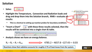
- 11. 11 ┬® 2017 ANSYS, Inc. May 10, 2017 Rt ŌĆō Rc ŌĆō Rr = Rtot 4785.2 ŌĆō 4657.8 ŌĆō127.43 = -0.03 ŌĆó Solve: ŌĆó Highlight the Temperature, Convection and Radiation loads and drag and drop them into the Solution branch, RMB > evaluate all results: ŌĆó This is a shortcut to setting up reaction probes for boundary conditions. ŌĆó ŌĆ£Insert a ChartŌĆØ with these three results selected, then the results will be combined into a single chart & table. ŌĆó Analysis shows we have an energy balance. Reactions show that radiation accounts for roughly 2.7% of heat losses from the system. Solution
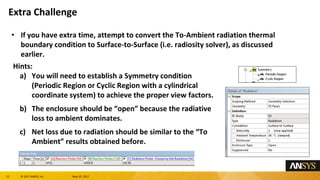
- 12. 12 ┬® 2017 ANSYS, Inc. May 10, 2017 ŌĆó If you have extra time, attempt to convert the To-Ambient radiation thermal boundary condition to Surface-to-Surface (i.e. radiosity solver), as discussed earlier. Hints: a) You will need to establish a Symmetry condition (Periodic Region or Cyclic Region with a cylindrical coordinate system) to achieve the proper view factors. b) The enclosure should be ŌĆ£openŌĆØ because the radiative loss to ambient dominates. c) Net loss due to radiation should be similar to the ŌĆ£To AmbientŌĆØ results obtained before. Extra Challenge


