Structure analysis assignment 7 frame analysis
1 like1,679 views

Assignment related to Structure analysis to determine the reactions and to draw axial force, shear force and bending moment diagrams for the members of statically determinate frames.
1 of 3
Download to read offline
Recommended
Calculation template
Calculation templateYekian Ian
╠²
The document provides calculations for load distributions on beams supporting multiple slabs in a building. It calculates the permanent and variable actions on each slab based on the self-weight of materials. These loads are then distributed to the beams below. Bending moments and shear forces are calculated for each beam span under maximum loading conditions using a finite element method. Reactions and uniform loading values are also determined for each span.Structure analysis assignment 7 determinate frame analysis
Structure analysis assignment 7 determinate frame analysisThe University of Lahore
╠²
This document contains 10 questions about drawing shear, moment and axial force diagrams for determinate frames with various support conditions. For each question, students are asked to draw the diagrams for each frame member and the elastic curve. The frames have different connections at their supports including pin, roller, and hinged and the documents provides the conditions for each question.Chapter 18(beams of composite materials)
Chapter 18(beams of composite materials)himachal pradesh technical university
╠²
- The document discusses stress analysis of composite beams made of two materials like concrete and steel.
- It explains the concept of transforming the cross-section of the composite beam into an equivalent cross-section of one material using the modular ratio.
- The maximum stresses in each material can then be calculated from the transformed section and adjusted using the modular ratio to get the true stresses.Chapter 07 in som 
Chapter 07 in som University Malaysia Pahang
╠²
This document contains solutions to problems involving the calculation of shear stresses in beams. It determines shear stresses at specific points of beams by using the shear formula and calculating the shear force resisted by various beam components. The maximum shear stress in several beams is also calculated. Cross-sectional properties like moment of inertia are used. Shear stresses are indicated on volume elements and shear force diagrams are sketched.Sheet 1 pressure measurments
Sheet 1 pressure measurmentsasomah
╠²
The document contains 7 problems involving the use of manometers and pressure calculations:
1) Calculating pressure differences using the formula for pressure as a function of depth and density.
2) Finding the pressure at the bottom of a lake using atmospheric pressure and the lake depth.
3) Calculating a pressure difference using a U-tube manometer filled with water and connected between two points in a pipe carrying air.
4) Determining the additional pressure needed to raise the liquid interface in a complicated U-tube manometer system containing two liquids of different densities.
5) Using a U-tube manometer containing mercury to determine the pressure reading of a pressure gauge, given column heights ofProblems on Torsion
Problems on Torsionsushma chinta
╠²
The document contains 8 questions related to determining the diameter of solid and hollow shafts based on transmitted power, torque, maximum shear stress, and angle of twist specifications. The questions involve calculating shaft diameters, transmitted torque values, shear stresses, and comparing weights of solid versus hollow shaft designs.Flexural design of beam...PRC-I
Flexural design of beam...PRC-IIrfan Malik
╠²
Prepared by madam rafia firdous. She is a lecturer and instructor in subject of Plain and Reinforcement concrete at University of South Asia LAHORE,PAKISTAN.09 review
09 reviewLiezel Abante
╠²
This document discusses moments of inertia, which are a measure of an object's resistance to rotational acceleration about an axis. It defines the moment of inertia of an area and introduces key concepts like the parallel axis theorem, radius of gyration, and calculating moments of inertia through integration or for composite areas. Examples are provided to demonstrate calculating moments of inertia for various shapes, including rectangles, triangles, L-shapes, and composite profiles, about different axes. The document also covers determining moments of inertia at the centroidal axes versus other axes using the parallel axis theorem.Structural Analysis, Hibbeler, 8th ed Textbook 
Structural Analysis, Hibbeler, 8th ed Textbook Bahzad5
╠²
This document provides tables and equations for analyzing beam deflections and slopes for various types of beams. It includes equations to determine the deflection (u), slope (v), maximum deflection (umax), and maximum slope (vmax) at different locations along beams subjected to a combination of loads, including concentrated forces (P), uniformly distributed loads (w), and moments (M). It also provides equations for determining deflections and slopes of beams with variable cross sections.Fluid tutorial 3
Fluid tutorial 3dr walid
╠²
1- In Fig. fluid 1 is oil (ĒæåĒÉ║ = 0.87) and fluid 2 is glycerin at 20┬░C (SG =1.26). If ĒæāĒæÄ = 98 ĒæśĒæāĒæÄ, Determine the absolute pressure at point ĒÉ┤. Inertia formulas
Inertia formulasManalNebhani
╠²
This document provides formulas for calculating the moment of inertia for common shapes about different axes. It gives the moment of inertia formulas for rectangles, triangles, circles, semi-circles, and ellipses. The formulas treat the moment of inertia about axes through the centroid (overbar notation) and parallel axes theorems which allow calculating the moment of inertia about any other axis given the distance from the centroidal axis.Steel warehouse design report
Steel warehouse design reportHavit Steel Structure Co.,ltd
╠²
Qingdao Havit Steel Structure design and fabricated Steel Building,Steel Warehouse,Steel Workshop,Prefab Steel Building,Steel Shed,Garage in ChinaChapter 7
Chapter 7Neagal Shu
╠²
#engineering #mechanics #masteringengineering #mastering #automotive #dynamics #statics #solutions #answers #chapter7 #internalloadingsdevelopedinstructuralmembers #internal #loadings #developed #structural #members #force #moment #engineeringmechanics #hibbeler #14thedition #13thedition #12th edition Solution of Chapter- 04 - shear & moment in beams - Strength of Materials by ...
Solution of Chapter- 04 - shear & moment in beams - Strength of Materials by ...Ashiqur Rahman Ziad
╠²
This document discusses shear and moment in beams. It defines statically determinate and indeterminate beams. It describes types of loading that can be applied to beams including concentrated loads, uniform loads, and varying loads. It discusses how to calculate and draw shear and moment diagrams for beams with different loading conditions. It explains the relationship between load, shear, and moment and how the slope of the shear and moment diagrams relates to one another. It also addresses moving loads and how to calculate the maximum shear and moment for beams with moving single or multiple loads.AASHTO LRFD Bridge Design Specifications (9th Edition).pdf
AASHTO LRFD Bridge Design Specifications (9th Edition).pdfKarin Faust
╠²
This document is the introduction to the 2020 American Association of State Highway and Transportation Officials Load and Resistance Factor Design Bridge Design Specifications. It discusses the history of bridge design standards in the United States dating back to 1931. It notes that the current specifications needed to be updated to incorporate advances in engineering knowledge, new materials, and the load and resistance factor design philosophy which better accounts for variability in loads and structural resistance. The introduction provides background on different design philosophies including working stress design, load factor design, and load and resistance factor design.StructuralTheoryClass2.ppt
StructuralTheoryClass2.pptChristopherArce4
╠²
The document discusses the double integration method for determining beam deflections. It defines beam deflection as the displacement of the beam's neutral surface from its original unloaded position. The differential equation relating the bending moment, flexural rigidity, and slope of the elastic curve is derived. This equation is integrated twice to obtain expressions for the slope and deflection of the beam in terms of the bending moment and constants of integration. Several examples are provided to demonstrate solving for the slope and maximum deflection of beams under different loading conditions using this method.Torsion Hollow Shaft
Torsion Hollow Shafttejasp
╠²
This document provides an overview of torsion and power transmission in shafts. It defines the torsion equation that relates torque, shear stress, polar second moment of area, and angle of twist. Formulas are derived for solid and hollow circular shafts. Examples are provided to calculate shear stress, angle of twist, and maximum torque or power given various shaft properties and limitations. The document also relates mechanical power to torque and rotational speed.Mechanics of Materials 8th Edition R.C. Hibbeler
Mechanics of Materials 8th Edition R.C. HibbelerBahzad5
╠²
This document describes a new type of battery that is safer and longer lasting than current lithium-ion batteries. It works by using sodium ions rather than lithium ions and two different metals as the electrodes. Sodium ions are able to flow back and forth between the electrodes through an electrolyte during charging and discharging. This new battery design could enable electric vehicles to travel further on a single charge and reduce the risk of fires.Influence lines (structural analysis theories)
Influence lines (structural analysis theories)Madujith Sagara
╠²
1. Influence lines represent the variation of reaction, shear, or moment at a specific point on a structural member as a concentrated load moves along the member. They are useful for analyzing the effects of moving loads.
2. To construct an influence line, a unit load is placed at different points along the member and the reaction, shear, or moment is calculated at the point of interest using statics. The values are plotted to show the influence of the load.
3. Influence lines allow engineers to determine the maximum value of a response (reaction, shear, moment) caused by a moving load and locate where on the structure that maximum occurs.Hibbeler ŌĆō Engineering Mechanics ŌĆō Statics 12th Edition Solution Manual
Hibbeler ŌĆō Engineering Mechanics ŌĆō Statics 12th Edition Solution ManualBahzad5
╠²
This document provides examples of solving mechanics problems involving forces and their components. It includes resolving forces into rectangular components, determining the magnitude and direction of resultant forces, and solving for unknown forces given components or the resultant. Several problems ask the reader to resolve forces into components, calculate resultant forces, or determine unknown forces based on given information about components and resultants. The document demonstrates techniques for solving static equilibrium problems involving two or more forces. Determinate structures
Determinate structuresTarun Gehlot
╠²
The document discusses the analysis of statically determinate structures, including defining idealized structures, explaining the principle of superposition and equations of equilibrium, classifying structures as determinate or indeterminate, and providing examples of determining reactions on beams and frames through applying the equations of equilibrium.Columns under eccentric loading
Columns under eccentric loadingcivilengineeringfreedownload
╠²
The document discusses different failure modes of columns under eccentric loading. It defines equations for determining the load carrying capacity (Pn) and moment capacity (Mn) of columns. Three failure cases are analyzed: 1) pure axial load/crushing failure where only compression steel contributes, 2) balanced failure where steel yields in tension and compression, and 3) pure flexural failure where the column acts like a beam with no axial load. Equations are derived for Pn and Mn for each case.STRAIN ENERGY CONCEPT STRENGTH OF MATERIAL
STRAIN ENERGY CONCEPT STRENGTH OF MATERIALdhavalprajapati100
╠²
1. Strain energy is the energy stored in a body when it is strained within the elastic limit due to an applied load. The formula for strain energy is U = Žā2/2E x V, where U is strain energy, Žā is stress, E is modulus of elasticity, and V is volume.
2. Resilience is the total strain energy stored in a body within the elastic limit. Proof resilience is the maximum strain energy that can be stored at the elastic limit. Modulus of resilience is the maximum strain energy that can be stored per unit volume at the elastic limit.
3. An impact or shock load is a sudden load applied to a body, such as a load falling from
Ecuacion para calculo del area de acero de una viga a flexionHarry Eyving Cifuentes Garcia
╠²
Para calcular la secci├│n de acero requerida en una viga rectangular sometida a flexi├│n, se utiliza una expresi├│n que considera la resistencia a la compresi├│n del concreto, el ancho y profundidad de la secci├│n, la distancia al acero desde la fibra m├Īs comprimida, y el ├Īrea y resistencia del acero. Esta expresi├│n equilibra el momento flector aplicado con la resistencia a flexi├│n proporcionada por el concreto y el acero.Lecture 07 som 04.03.2021
Lecture 07 som 04.03.2021BIBIN CHIDAMBARANATHAN
╠²
The document discusses the principle of superposition for calculating deformation of elastic materials under multiple loads. It provides an example problem of calculating the total elongation of a brass bar subjected to various axial forces along its length. The bar is divided into three sections and the forces acting on each section are identified. The formula for total deformation is given as the sum of the individual deformations of each section. For the sample problem, the forces on the three sections are determined and the total elongation is calculated as a decrease of 0.114 mm using the given properties of the bar material.Design methods for torsional buckling of steel structures
Design methods for torsional buckling of steel structuresBegum Emte Ajom
╠²
The document discusses methods for designing steel structures to resist torsional buckling. It summarizes clauses from Eurocode 3 that provide equations for calculating the elastic critical buckling moment and determining the reduction factor used to calculate the design bending strength. It also presents simplified equations that can be used to calculate the elastic critical buckling moment for common steel beam sections. Additional guidance is provided for calculating the critical buckling moment for non-symmetric sections and when bending occurs about the major axis.Design of Beam for Shear
Design of Beam for Shearillpa
╠²
The document discusses shear design of beams. It covers shear strength, which depends on the web thickness and h/t ratio to prevent shear buckling. Shear strength is calculated as 60% of the tensile yield stress. Block shear failure is also discussed, where the strength is governed by the shear and net tension areas. An example calculates the maximum reaction based on block shear for a coped beam connection.Solved problems pipe flow final 1.doc
Solved problems pipe flow final 1.docDr. Ezzat Elsayed Gomaa
╠²
1. The document contains worked examples of calculating flow rates and head losses in pipe systems with one or more pipes connected in parallel.
2. In Example 1, the ratio of flow rates in two parallel pipes of identical diameter is calculated to be the inverse ratio of their lengths.
3. Example 4 involves calculating the maximum length of the first portion of a pipe connecting two reservoirs given the change in pressure head and system parameters. The energy equation and head loss equations for each pipe section are used.Structure analysis assignment 9 moment distribution method frame
Structure analysis assignment 9 moment distribution method frameThe University of Lahore
╠²
Assignment related to Structure analysis to determine the reactions and to draw axial force, shear force and bending moment diagrams for the members of statically indeterminate frames by moment distribution methodStructure analysis assignment 8 moment distribution method beam
Structure analysis assignment 8 moment distribution method beamThe University of Lahore
╠²
Assignment related to Structure analysis to determine the reactions and to draw shear force and bending moment diagrams for statically indeterminate beams by moment distribution methodMore Related Content
What's hot (20)
Structural Analysis, Hibbeler, 8th ed Textbook
Structural Analysis, Hibbeler, 8th ed Textbook Bahzad5
╠²
This document provides tables and equations for analyzing beam deflections and slopes for various types of beams. It includes equations to determine the deflection (u), slope (v), maximum deflection (umax), and maximum slope (vmax) at different locations along beams subjected to a combination of loads, including concentrated forces (P), uniformly distributed loads (w), and moments (M). It also provides equations for determining deflections and slopes of beams with variable cross sections.Fluid tutorial 3
Fluid tutorial 3dr walid
╠²
1- In Fig. fluid 1 is oil (ĒæåĒÉ║ = 0.87) and fluid 2 is glycerin at 20┬░C (SG =1.26). If ĒæāĒæÄ = 98 ĒæśĒæāĒæÄ, Determine the absolute pressure at point ĒÉ┤. Inertia formulas
Inertia formulasManalNebhani
╠²
This document provides formulas for calculating the moment of inertia for common shapes about different axes. It gives the moment of inertia formulas for rectangles, triangles, circles, semi-circles, and ellipses. The formulas treat the moment of inertia about axes through the centroid (overbar notation) and parallel axes theorems which allow calculating the moment of inertia about any other axis given the distance from the centroidal axis.Steel warehouse design report
Steel warehouse design reportHavit Steel Structure Co.,ltd
╠²
Qingdao Havit Steel Structure design and fabricated Steel Building,Steel Warehouse,Steel Workshop,Prefab Steel Building,Steel Shed,Garage in ChinaChapter 7
Chapter 7Neagal Shu
╠²
#engineering #mechanics #masteringengineering #mastering #automotive #dynamics #statics #solutions #answers #chapter7 #internalloadingsdevelopedinstructuralmembers #internal #loadings #developed #structural #members #force #moment #engineeringmechanics #hibbeler #14thedition #13thedition #12th edition Solution of Chapter- 04 - shear & moment in beams - Strength of Materials by ...
Solution of Chapter- 04 - shear & moment in beams - Strength of Materials by ...Ashiqur Rahman Ziad
╠²
This document discusses shear and moment in beams. It defines statically determinate and indeterminate beams. It describes types of loading that can be applied to beams including concentrated loads, uniform loads, and varying loads. It discusses how to calculate and draw shear and moment diagrams for beams with different loading conditions. It explains the relationship between load, shear, and moment and how the slope of the shear and moment diagrams relates to one another. It also addresses moving loads and how to calculate the maximum shear and moment for beams with moving single or multiple loads.AASHTO LRFD Bridge Design Specifications (9th Edition).pdf
AASHTO LRFD Bridge Design Specifications (9th Edition).pdfKarin Faust
╠²
This document is the introduction to the 2020 American Association of State Highway and Transportation Officials Load and Resistance Factor Design Bridge Design Specifications. It discusses the history of bridge design standards in the United States dating back to 1931. It notes that the current specifications needed to be updated to incorporate advances in engineering knowledge, new materials, and the load and resistance factor design philosophy which better accounts for variability in loads and structural resistance. The introduction provides background on different design philosophies including working stress design, load factor design, and load and resistance factor design.StructuralTheoryClass2.ppt
StructuralTheoryClass2.pptChristopherArce4
╠²
The document discusses the double integration method for determining beam deflections. It defines beam deflection as the displacement of the beam's neutral surface from its original unloaded position. The differential equation relating the bending moment, flexural rigidity, and slope of the elastic curve is derived. This equation is integrated twice to obtain expressions for the slope and deflection of the beam in terms of the bending moment and constants of integration. Several examples are provided to demonstrate solving for the slope and maximum deflection of beams under different loading conditions using this method.Torsion Hollow Shaft
Torsion Hollow Shafttejasp
╠²
This document provides an overview of torsion and power transmission in shafts. It defines the torsion equation that relates torque, shear stress, polar second moment of area, and angle of twist. Formulas are derived for solid and hollow circular shafts. Examples are provided to calculate shear stress, angle of twist, and maximum torque or power given various shaft properties and limitations. The document also relates mechanical power to torque and rotational speed.Mechanics of Materials 8th Edition R.C. Hibbeler
Mechanics of Materials 8th Edition R.C. HibbelerBahzad5
╠²
This document describes a new type of battery that is safer and longer lasting than current lithium-ion batteries. It works by using sodium ions rather than lithium ions and two different metals as the electrodes. Sodium ions are able to flow back and forth between the electrodes through an electrolyte during charging and discharging. This new battery design could enable electric vehicles to travel further on a single charge and reduce the risk of fires.Influence lines (structural analysis theories)
Influence lines (structural analysis theories)Madujith Sagara
╠²
1. Influence lines represent the variation of reaction, shear, or moment at a specific point on a structural member as a concentrated load moves along the member. They are useful for analyzing the effects of moving loads.
2. To construct an influence line, a unit load is placed at different points along the member and the reaction, shear, or moment is calculated at the point of interest using statics. The values are plotted to show the influence of the load.
3. Influence lines allow engineers to determine the maximum value of a response (reaction, shear, moment) caused by a moving load and locate where on the structure that maximum occurs.Hibbeler ŌĆō Engineering Mechanics ŌĆō Statics 12th Edition Solution Manual
Hibbeler ŌĆō Engineering Mechanics ŌĆō Statics 12th Edition Solution ManualBahzad5
╠²
This document provides examples of solving mechanics problems involving forces and their components. It includes resolving forces into rectangular components, determining the magnitude and direction of resultant forces, and solving for unknown forces given components or the resultant. Several problems ask the reader to resolve forces into components, calculate resultant forces, or determine unknown forces based on given information about components and resultants. The document demonstrates techniques for solving static equilibrium problems involving two or more forces. Determinate structures
Determinate structuresTarun Gehlot
╠²
The document discusses the analysis of statically determinate structures, including defining idealized structures, explaining the principle of superposition and equations of equilibrium, classifying structures as determinate or indeterminate, and providing examples of determining reactions on beams and frames through applying the equations of equilibrium.Columns under eccentric loading
Columns under eccentric loadingcivilengineeringfreedownload
╠²
The document discusses different failure modes of columns under eccentric loading. It defines equations for determining the load carrying capacity (Pn) and moment capacity (Mn) of columns. Three failure cases are analyzed: 1) pure axial load/crushing failure where only compression steel contributes, 2) balanced failure where steel yields in tension and compression, and 3) pure flexural failure where the column acts like a beam with no axial load. Equations are derived for Pn and Mn for each case.STRAIN ENERGY CONCEPT STRENGTH OF MATERIAL
STRAIN ENERGY CONCEPT STRENGTH OF MATERIALdhavalprajapati100
╠²
1. Strain energy is the energy stored in a body when it is strained within the elastic limit due to an applied load. The formula for strain energy is U = Žā2/2E x V, where U is strain energy, Žā is stress, E is modulus of elasticity, and V is volume.
2. Resilience is the total strain energy stored in a body within the elastic limit. Proof resilience is the maximum strain energy that can be stored at the elastic limit. Modulus of resilience is the maximum strain energy that can be stored per unit volume at the elastic limit.
3. An impact or shock load is a sudden load applied to a body, such as a load falling fromEcuacion para calculo del area de acero de una viga a flexionHarry Eyving Cifuentes Garcia
╠²
Para calcular la secci├│n de acero requerida en una viga rectangular sometida a flexi├│n, se utiliza una expresi├│n que considera la resistencia a la compresi├│n del concreto, el ancho y profundidad de la secci├│n, la distancia al acero desde la fibra m├Īs comprimida, y el ├Īrea y resistencia del acero. Esta expresi├│n equilibra el momento flector aplicado con la resistencia a flexi├│n proporcionada por el concreto y el acero.Lecture 07 som 04.03.2021
Lecture 07 som 04.03.2021BIBIN CHIDAMBARANATHAN
╠²
The document discusses the principle of superposition for calculating deformation of elastic materials under multiple loads. It provides an example problem of calculating the total elongation of a brass bar subjected to various axial forces along its length. The bar is divided into three sections and the forces acting on each section are identified. The formula for total deformation is given as the sum of the individual deformations of each section. For the sample problem, the forces on the three sections are determined and the total elongation is calculated as a decrease of 0.114 mm using the given properties of the bar material.Design methods for torsional buckling of steel structures
Design methods for torsional buckling of steel structuresBegum Emte Ajom
╠²
The document discusses methods for designing steel structures to resist torsional buckling. It summarizes clauses from Eurocode 3 that provide equations for calculating the elastic critical buckling moment and determining the reduction factor used to calculate the design bending strength. It also presents simplified equations that can be used to calculate the elastic critical buckling moment for common steel beam sections. Additional guidance is provided for calculating the critical buckling moment for non-symmetric sections and when bending occurs about the major axis.Design of Beam for Shear
Design of Beam for Shearillpa
╠²
The document discusses shear design of beams. It covers shear strength, which depends on the web thickness and h/t ratio to prevent shear buckling. Shear strength is calculated as 60% of the tensile yield stress. Block shear failure is also discussed, where the strength is governed by the shear and net tension areas. An example calculates the maximum reaction based on block shear for a coped beam connection.Solved problems pipe flow final 1.doc
Solved problems pipe flow final 1.docDr. Ezzat Elsayed Gomaa
╠²
1. The document contains worked examples of calculating flow rates and head losses in pipe systems with one or more pipes connected in parallel.
2. In Example 1, the ratio of flow rates in two parallel pipes of identical diameter is calculated to be the inverse ratio of their lengths.
3. Example 4 involves calculating the maximum length of the first portion of a pipe connecting two reservoirs given the change in pressure head and system parameters. The energy equation and head loss equations for each pipe section are used.Solution of Chapter- 04 - shear & moment in beams - Strength of Materials by ...
Solution of Chapter- 04 - shear & moment in beams - Strength of Materials by ...Ashiqur Rahman Ziad
╠²
More from The University of Lahore (9)
Structure analysis assignment 9 moment distribution method frame
Structure analysis assignment 9 moment distribution method frameThe University of Lahore
╠²
Assignment related to Structure analysis to determine the reactions and to draw axial force, shear force and bending moment diagrams for the members of statically indeterminate frames by moment distribution methodStructure analysis assignment 8 moment distribution method beam
Structure analysis assignment 8 moment distribution method beamThe University of Lahore
╠²
Assignment related to Structure analysis to determine the reactions and to draw shear force and bending moment diagrams for statically indeterminate beams by moment distribution methodStructure analysis assignment 6 shear-force bending moment in beams
Structure analysis assignment 6 shear-force bending moment in beamsThe University of Lahore
╠²
Assignment related to Structure analysis to determine the shear force and bending moment diagrams for statically determinate beams..Structure analysis assignment 5 analysis of statically determinate truss
Structure analysis assignment 5 analysis of statically determinate trussThe University of Lahore
╠²
Assignment related to Structure analysis to determine the forces in the members of truss by joint method as well as section method.Structure analysis assignment 4 centroid-moment of inertia
Structure analysis assignment 4 centroid-moment of inertiaThe University of Lahore
╠²
Assignment related to Structure analysis to determine the centroid and moment of inertia for different geometric shapes. Structure analysis assignment 3 support reaction calculation
Structure analysis assignment 3 support reaction calculationThe University of Lahore
╠²
Assignment related to structure analysis to determine the support reaction of beams, truss and frames by using equations of equilibrium. Structure analysis assignment 2 determinacy and stability
Structure analysis assignment 2 determinacy and stabilityThe University of Lahore
╠²
Assignment related to structure analysis to check weather the given structure is determinate or indeterminate and stable or unstableStructure analysis assignment 1 load-calculation
Structure analysis assignment 1 load-calculationThe University of Lahore
╠²
This document contains 5 questions regarding calculating loads on structural members. Question 1 asks to calculate and sketch the factored load on members BE and FED of an office building with a 5 inch concrete slab, using dimensions of 20ft by 15ft. Question 2 asks to do the same for members BG and ABCD of a residential building with a 7 inch wood deck, using dimensions of 5ft by 10ft. Question 3 asks to sketch the loading on girder ABCDE of a school with a 6 inch concrete slab, using dimensions of 7.5ft by 20ft. Question 4 asks to calculate the factored load on column A of a school with a 6 inch concrete slab, using dimensions of 7ft by 10ftAutoCAD Lecture-1 How to install Autocad
AutoCAD Lecture-1 How to install AutocadThe University of Lahore
╠²
The document discusses how to install and activate AutoCAD 2008 software. It was written by Engr. Atiq Ur Rehman, who works in the Department of Civil Engineering at the University of Lahore. The document repeats information about the author and department. It also mentions activating AutoCAD 2008 but does not provide any instructions for installing or activating the software.Recently uploaded (20)
Production Planning & Control and Inventory Management.pptx
Production Planning & Control and Inventory Management.pptxVirajPasare
╠²
Production Planning and Control : Importance, Objectives and Functions . Inventory Management - Meaning, Types , Objectives, Selective Inventory Control : ABC AnalysisUnit-03 Cams and Followers in Mechanisms of Machines.pptx
Unit-03 Cams and Followers in Mechanisms of Machines.pptxKirankumar Jagtap
╠²
Unit-03 Cams and Followers.pptxKnowledge-Based Agents in AI: Principles, Components, and Functionality
Knowledge-Based Agents in AI: Principles, Components, and FunctionalityRashmi Bhat
╠²
This PowerPoint presentation provides an in-depth exploration of Knowledge-Based Agents (KBAs) in Artificial Intelligence (AI). It explains how these agents make decisions using stored knowledge and logical reasoning rather than direct sensor input. The presentation covers key components such as the Knowledge Base (KB), Inference Engine, Perception, and Action Execution.
Key topics include:
Ō£ģ Definition and Working Mechanism of Knowledge-Based Agents
Ō£ģ The Process of TELL, ASK, and Execution in AI Agents
Ō£ģ Representation of Knowledge and Decision-Making Approaches
Ō£ģ Logical Inference and Rule-Based Reasoning
Ō£ģ Applications of Knowledge-Based Agents in Real-World AI
This PPT is useful for students, educators, and AI enthusiasts who want to understand how intelligent agents operate using stored knowledge and logic-based inference. The slides are well-structured with explanations, examples, and an easy-to-follow breakdown of AI agent functions.Airport Components Part2 ppt.pptx-Apron,Hangers,Terminal building
Airport Components Part2 ppt.pptx-Apron,Hangers,Terminal buildingPriyanka Dange
╠²
Apron,Hangers,Terminal building
Why the Engineering Model is Key to Successful Projects
Why the Engineering Model is Key to Successful ProjectsMaadhu Creatives-Model Making Company
╠²
In this PDF document, the importance of engineering models in successful project execution is discussed. It explains how these models enhance visualization, planning, and communication. Engineering models help identify potential issues early, reducing risks and costs. Ultimately, they improve collaboration and client satisfaction by providing a clear representation of the project.Software security: Security a Software Issue
Software security: Security a Software IssueDr Sarika Jadhav
╠²
Software is often designed with security as an afterthought, leading to vulnerabilities that can be exploited by attackers. This has become a critical issue as our reliance on software continues to grow.
Increasing number and sophistication of attacks (CERT vulnerability reports rising).
Software security is the practice of protecting applications from unauthorized access, modification, and destruction.
Secure software development practices.
Executives (E)
Project Managers (M)
Technical Leaders (L)
Introduction to 3D Printing Technology.pptx
Introduction to 3D Printing Technology.pptxpprakash21252
╠²
Welcome to our presentation on 3D printing technology, where we explore the transformative power of this innovative manufacturing process. Also known as additive manufacturing, 3D printing has been gaining momentum in recent years, and its potential to revolutionize industries is vast.
In this presentation, we delve into the world of 3D printing, discussing its history, principles, and applications. We examine the various types of 3D printing technologies, including Fused Deposition Modeling (FDM), Stereolithography (SLA), and Selective Laser Sintering (SLS). We also explore the advantages and limitations of 3D printing, including its ability to create complex geometries, reduce material waste, and increase product customization.
One of the most significant impacts of 3D printing is its potential to transform industries. We discuss the applications of 3D printing in various sectors, including aerospace, automotive, healthcare, and consumer products. We examine case studies of companies that have successfully implemented 3D printing, such as Boeing, BMW, and Procter & Gamble.
The presentation also explores the future of 3D printing, including emerging trends and technologies. We discuss the potential of 3D printing to disrupt traditional supply chains and create new business models. We also examine the challenges and limitations of 3D printing, including the need for standardization, regulation, and education.
This presentation is ideal for anyone interested in learning about 3D printing technology, including students, researchers, entrepreneurs, and industry professionals. Whether you are looking to gain a basic understanding of 3D printing or seeking to explore its applications in various industries, this presentation is a valuable resource.
Scalling Rails: The Journey to 200M Notifications
Scalling Rails: The Journey to 200M NotificationsGustavo Araujo
╠²
Talk presented at Tropical On Rails.LA2-64 -bit assemby language program to count number of positive and negative...
LA2-64 -bit assemby language program to count number of positive and negative...VidyaAshokNemade
╠²
This is one of lab experiment for Microprocessor UHV UNIT-5 IMPLICATIONS OF THE ABOVE HOLISTIC UNDERSTANDING OF HARMONY ON ...
UHV UNIT-5 IMPLICATIONS OF THE ABOVE HOLISTIC UNDERSTANDING OF HARMONY ON ...ariomthermal2031
╠²
IMPLICATIONS OF THE ABOVE HOLISTIC UNDERSTANDING OF HARMONY ON PROFESSIONAL ETHICS Hackathon-Problem-Statements-Technology-Track-with-Link.pptx
Hackathon-Problem-Statements-Technology-Track-with-Link.pptxdatahiverecruitment
╠²
Hackathon-Problem-Statements-Technology-Track-with-Link.pptxAnalysis of Daylighting in Interior Spaces using the Daylight Factor - A Manu...
Analysis of Daylighting in Interior Spaces using the Daylight Factor - A Manu...Ignacio J. J. Palma Carazo
╠²
Daylighting manual method based on Daylight Factor for indoor spaces, previous to any computational simulation method.Requirements Engineering for Secure Software
Requirements Engineering for Secure SoftwareDr Sarika Jadhav
╠²
Security requirements are often treated as generic lists of features, neglecting system-specific needs and the attacker's perspective. A systematic approach to security requirements engineering is crucial to avoid this problem.
Requirements engineering defects can cost 10 to 200 times more to correct once the system is operational. Software development takes place in a dynamic environment, causing requirements to constantly change.
Airport Components Part1 ppt.pptx-Site layout,RUNWAY,TAXIWAY,TAXILANE
Airport Components Part1 ppt.pptx-Site layout,RUNWAY,TAXIWAY,TAXILANEPriyanka Dange
╠²
RUNWAY,TAXIWAY,TAXILANETelehealth technology ŌĆō A new horizon in health care
Telehealth technology ŌĆō A new horizon in health careDr INBAMALAR T M
╠²
Telehealth technology ŌĆō A new horizon in health care, Telemedicine, E-health
Intro of Airport Engg..pptx-Definition of airport engineering and airport pla...
Intro of Airport Engg..pptx-Definition of airport engineering and airport pla...Priyanka Dange
╠²
Definition of airport engineering and airport planning, Types of surveys required for airport site, Factors affecting the selection of site for AirportChapter1-Introduction ╬Ģ╬╣Žā╬▒╬│Žē╬│╬╣╬║╬ŁŽé ╬Ł╬Į╬Į╬┐╬╣╬ĄŽé
Chapter1-Introduction ╬Ģ╬╣Žā╬▒╬│Žē╬│╬╣╬║╬ŁŽé ╬Ł╬Į╬Į╬┐╬╣╬ĄŽéssuserb91a20
╠²
╬Ģ╬╣Žā╬▒╬│Žē╬│╬╣╬║Žī ╬║╬ĄŽå╬¼╬╗╬▒╬╣╬┐UHV Unit - 4 HARMONY IN THE NATURE AND EXISTENCE.pptx
UHV Unit - 4 HARMONY IN THE NATURE AND EXISTENCE.pptxariomthermal2031
╠²
HARMONY IN THE NATURE AND EXISTENCE Analysis of Daylighting in Interior Spaces using the Daylight Factor - A Manu...
Analysis of Daylighting in Interior Spaces using the Daylight Factor - A Manu...Ignacio J. J. Palma Carazo
╠²
Structure analysis assignment 7 frame analysis
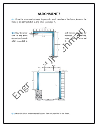
- 1. ASSIGNMENT-7 Q-1: Draw the shear and moment diagrams for each member of the frame. Assume the frame is pin connected at C, and roller connected A. Q-2: Draw the shear and moment diagrams for each of the three members of the frame. Assume the frame is hinge connected at A and roller connected at D. Q-3: Draw the shear and moment diagrams for each member of the frame.
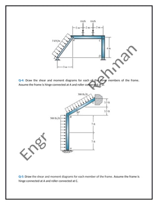
- 2. Q-4: Draw the shear and moment diagrams for each of the three members of the frame. Assume the frame is hinge connected at A and roller connected at D. Q-5: Draw the shear and moment diagrams for each member of the frame. Assume the frame is hinge connected at A and roller connected at C.