Structure analysis assignment 3 support reaction calculation
2 likes750 views

Assignment related to structure analysis to determine the support reaction of beams, truss and frames by using equations of equilibrium.
1 of 4
Download to read offline

Recommended
Structure analysis assignment 7 determinate frame analysis
Structure analysis assignment 7 determinate frame analysisThe University of Lahore
╠²
This document contains 10 questions about drawing shear, moment and axial force diagrams for determinate frames with various support conditions. For each question, students are asked to draw the diagrams for each frame member and the elastic curve. The frames have different connections at their supports including pin, roller, and hinged and the documents provides the conditions for each question.Structure analysis assignment 7 frame analysis
Structure analysis assignment 7 frame analysisThe University of Lahore
╠²
Assignment related to Structure analysis to determine the reactions and to draw axial force, shear force and bending moment diagrams for the members of statically determinate frames.Structure analysis assignment 6 shear-force bending moment in beams
Structure analysis assignment 6 shear-force bending moment in beamsThe University of Lahore
╠²
Assignment related to Structure analysis to determine the shear force and bending moment diagrams for statically determinate beams..Structure analysis assignment 4 centroid-moment of inertia
Structure analysis assignment 4 centroid-moment of inertiaThe University of Lahore
╠²
Assignment related to Structure analysis to determine the centroid and moment of inertia for different geometric shapes. Position analysis Norton 4e by Usama Yousuf
Position analysis Norton 4e by Usama YousufMuhammad Yousuf
╠²
The document discusses slider-crank mechanisms and their position analysis. It describes inline and offset slider-crank mechanisms and whether the crank or slider acts as the input link. It states that the problem involves computing the slider's position and an angle given the mechanism's link lengths, the slider's offset, and an input angle. Additionally, it covers inverted slider-cranks, four-bar mechanisms, and linkages with more than four bars, deriving equations for gear ratios and phase angles.3.1 GEAR TRAINS
3.1 GEAR TRAINSKiran Wakchaure
╠²
The document discusses different types of gear trains used to transmit motion between rotating shafts in machines. It describes simple gear trains which use a single gear on each shaft, compound gear trains which use multiple gears on a shaft, reverted gear trains where the first and last gears share a common axis of rotation, and epicyclic gear trains where gears move in an orbital path relative to a fixed axis. Epicyclic gear trains are useful for achieving high speed ratios within a compact space and are used in applications like lathes, differentials, hoists, and watches.Whitworth quick return mechanism
Whitworth quick return mechanismAmar Borkute
╠²
Sir Joseph Whitworth invented the Whitworth quick return mechanism in the 19th century to convert rotational motion into reciprocating linear motion. The mechanism uses four links - a fixed link, slotted bar, driving crank, and slider - to transform the rotation of a crank into the back-and-forth motion of a cutting tool. As the crank rotates clockwise and counterclockwise, the connected slider moves the tool across its stroke to shape or cut materials. This innovative mechanism is still used today in machine tools like shaper and slotter machines.2.4 bevel gear
2.4 bevel gearKiran Wakchaure
╠²
This document discusses bevel gears, which are useful for changing the direction of shaft rotation by 90 degrees. Bevel gears can have straight, spiral, or hypoid teeth and are commonly used in applications like locomotives, marine vessels, automobiles, and industrial machinery. The document explains the components of bevel gears like the pitch cone and cone center. It also discusses how to develop involute teeth on the cone surface of bevel gears. The advantages of bevel gears are also summarized, such as their quiet operation and high efficiency compared to other gear types.4.2 follower motion
4.2 follower motionKiran Wakchaure
╠²
This document discusses different types of follower motion in cam and follower mechanisms. It describes four standard types of follower motion: uniform velocity, simple harmonic motion, uniform acceleration and deceleration, and cycloidal motion. It also discusses displacement, velocity, and acceleration diagrams which plot the displacement, velocity, and acceleration of the follower against the angular displacement of the cam. These diagrams are used to analyze the motion of the follower in a cam and follower system. Key terms related to cam and follower mechanisms such as stroke, angular velocity, cam angle, and acceleration of the follower are also defined.Detail ppt on Scotch Yoke Mechanism.
Detail ppt on Scotch Yoke Mechanism.Mandar Gadkari
╠²
The Scotch yoke mechanism converts rotational motion to reciprocating motion, or vice versa, using a sliding yoke with a slot that engages a pin on the rotating part. It is more efficient than a crankshaft at producing rotational motion as it spends more time at the high point of rotation and has fewer parts. The mechanism finds applications in control valves, hacksaws, reciprocating pumps, and toys where reciprocating motion is required.Friction
FrictionDhammaratna Dabhade
╠²
This document discusses different types of friction including screw friction, pivot and collar bearing friction. It provides equations for calculating the torque required to lift and lower a load using a screw jack. It also discusses friction in v-threads and the assumptions made when analyzing pivot and collar bearings, specifically that pressure is uniformly distributed and wear is uniform. Pivot bearings are used to take axial thrust on rotating shafts in applications like ships and turbines. Collar bearings are flat surfaces that experience sliding friction where the shaft contacts the bearing.Deployable Tensegrity Robots Tel Aviv
Deployable Tensegrity Robots Tel AvivTensegrity Wiki
╠²
The document discusses deployable tensegrity robots based on tensegrity structures and Assur graphs. Tensegrity structures consist of cables that sustain tension and struts that sustain compression. Assur graphs are tensegrity frameworks that maintain self-stress in all elements without failing joints or singular positions from moving individual elements. The robots employ these properties by using cables, actuators, and control of cable lengths to change shapes while maintaining rigidity. Controlling a single cable brings the system to a singular position validated by the properties of Assur structures.Kinematics of-rigid-body
Kinematics of-rigid-bodysharancm2009
╠²
This document contains chapter materials from the textbook "Vector Mechanics for Engineers: Dynamics, Ninth Edition" regarding the kinematics of rigid bodies. It discusses various types of rigid body motion including translation, rotation about a fixed axis, general plane motion, and general motion. It provides definitions and equations for the velocity and acceleration of particles in a rigid body undergoing different types of motion, including examples calculating velocity, acceleration, and angular displacement over time. Key concepts covered include absolute and relative velocity and acceleration in plane motion, instantaneous centers of rotation, and the effects of rotating reference frames.ES3323 - Project 1 Report - Modeling Watt's Linkage
ES3323 - Project 1 Report - Modeling Watt's LinkageConstantine Christelis
╠²
This document describes the modeling of a Watt's straight-line linkage mechanism in Creo Parametric software. It provides background on straight-line mechanisms and the specific Watt linkage. Design calculations are shown to verify the mechanism has one degree of freedom. The modeling strategy involved creating individual parts, subassemblies, and applying constraints. Kinematic analysis of the full assembly found low deviations from straight-line motion of less than 0.0013 inches per vertical inch of the slider. The model accurately represented the intended straight-line motion of the Watt linkage mechanism.Crank Sliding Link Cylinder Mechanism
Crank Sliding Link Cylinder MechanismDhaval Shukla
╠²
In this ppt I have given the mechanism, functions and working of the Crank Sliding Link Cylinder Mechanism, the images in gif have been given for the viewers to understand thoroughly the concept of this topic and disadvantages and calculation.Quick return mechanism
Quick return mechanismSaif al-din ali
╠²
1. The document describes an experiment to construct a quick return mechanism using a linkage to transform uniform crank rotation into oscillating follower link motion and reciprocating slider motion.
2. Data was collected on crank angle versus slider displacement and plotted on a graph to analyze the quick motion of the mechanism.
3. It was found that the slider moves faster from right to left, with maximum velocity at 280 degrees crank angle and zero velocity at 240 degrees.Theory of machines
Theory of machinesSourabh Kumar
╠²
These type of presentation with GIF can never seen before, so it is very nice & give it to you in summarize form..thankyouBasic mechanical engineering (BMET-101/102) unit 4- part 2 (beams) by varun p...
Basic mechanical engineering (BMET-101/102) unit 4- part 2 (beams) by varun p...Varun Pratap Singh
╠²
Download Link: https://sites.google.com/view/varunpratapsingh/teaching-engagements (Copy URL)
Unit4 Part-2
Force system and Analysis
Basic concept: Review of laws of motion, transfer of force to parallel position, resultant of planer force system, Free Body Diagrams, Equilibrium. Friction: Introduction, Laws of Coulomb friction, Equilibrium of bodies involving dry fiction.
Mechanical motion
Mechanical motionJutka Czirok
╠²
Mechanisms are devices that use various types of motions and forces to make tasks easier. They convert one type of motion into another through linkages, levers, gears, and other components. Common types of motion include linear, rotary, intermittent, oscillating, and reciprocating. Examples of mechanisms that convert motion include rack and pinion gears, bell cranks, toggle clamps, cams, and linkages like parallel motion and treadle linkages.002 four bar linkages
002 four bar linkagesphysics101
╠²
The four-bar linkage is the simplest and most common type of linkage, consisting of four links connected by four pin joints. It has one degree of freedom and requires one driver to operate fully. The document discusses different configurations of four-bar linkages like the parallel-crank, nonparallel equal-crank, crank and rocker, and slider-crank mechanisms. Quick return mechanisms are also described which give a tool a slow cutting stroke and fast return stroke.Mechanical Joints in LS-Dyna for Explicit Analysis
Mechanical Joints in LS-Dyna for Explicit AnalysisAkshay Mistri
╠²
This document discusses different types of mechanical joints that can be modeled in LS-Dyna explicit analysis, including spherical, revolute, planar, and gear joints. It provides introductions and definitions for each joint type, along with examples of their motions and how they are defined using LS-Dyna keywords. Videos are included showing examples of each joint type in action under simulated loading conditions.Theory of mechanisms & machines final
Theory of mechanisms & machines finalEshwar Venkatesh
╠²
The document discusses a quick return mechanism, which converts rotary motion into reciprocating motion at different rates for the working and return strokes. It is commonly used in machine tools to improve productivity by making the return stroke faster than the working stroke. The mechanism consists of a driving crank and driven slider crank, where the fixed pivot of the driven crank is located outside the circle traced by the driving crank, resulting in alternating motion of the slider crank. Joseph Whitworth developed an early version of this mechanism around 1840 to increase the speed of shaping machines. It allows the return stroke of the cutting tool to be faster than the working stroke to reduce idle time.Introduction to Mechanisms
Introduction to MechanismsHareesha N Gowda, Dayananda Sagar College of Engg, Bangalore
╠²
Unit 1-introduction to Mechanisms, Kinematics of machines of VTU Syllabus prepared by Hareesha N Gowda, Asst. Prof, Dayananda Sagar College of Engg, Blore. Please write to hareeshang@gmail.com for suggestions and criticisms. 001 mechanisms and kinematics
001 mechanisms and kinematicsphysics101
╠²
The document discusses kinematics and mechanisms. It defines kinematics as the study of motion geometry and mechanisms as devices that transfer motion and forces. It describes the components of mechanisms including links, joints, frames and discusses revolute and sliding joints. Higher order joints like cam and gear joints are described. Degrees of freedom, which represent the number of independent inputs to position all links, are discussed along with Gruebler's equation for calculating degrees of freedom. Examples of kinematic diagrams for mechanisms are provided along with computing degrees of freedom.Basic mechanical engineering (BMET-101/102) unit 4- part1 (force system and a...
Basic mechanical engineering (BMET-101/102) unit 4- part1 (force system and a...Varun Pratap Singh
╠²
Download Link: https://sites.google.com/view/varunpratapsingh/teaching-engagements
Unit-4 Part -1
Force system and Analysis
Basic concept: Review of laws of motion, transfer of force to parallel position, resultant of planer force system, Free-Body Diagrams, Equilibrium. Friction: Introduction, Laws of Coulomb friction, Equilibrium of bodies involving dry fiction.
Shaper Machine Quick Return 6 Bar Mechanism Project by Industrial & Manufactu...
Shaper Machine Quick Return 6 Bar Mechanism Project by Industrial & Manufactu...Muhammad Umar Farooq
╠²
Shaper Machine Quick Return 6 Bar Mechanism Project by Industrial & Manufacturing Engineering Students.of UET Lahore, Pakistan2.3 worm and worm wheel
2.3 worm and worm wheelKiran Wakchaure
╠²
The document discusses worm gears and provides definitions and equations related to their design and operation. It defines worm gears as having large gear reductions from 20:1 up to 300:1. Worm gears are used widely in machinery because the worm can easily turn the gear but the gear cannot turn the worm. Key terms defined include lead, lead angle, velocity ratio, center distance, efficiency, and force equations. Design considerations like helix angle, module, and pitch are also addressed.Velocity & acceleration diagrams
Velocity & acceleration diagramssherin_ginige
╠²
This document provides an introduction to kinematics and the analysis of mechanisms using velocity and acceleration diagrams. It discusses:
1. Key concepts in mechanisms including different types of motion transformations and common mechanism components like four-bar linkages.
2. How to determine the displacement, velocity, and acceleration of points within a mechanism using either mathematical equations or graphical methods using velocity and acceleration diagrams.
3. How to construct velocity diagrams by determining the absolute and relative velocities of points and drawing them as vectors. This allows solving for unknown velocities.
4. How to extend the method to acceleration diagrams to determine centripetal and other accelerations which are important for calculating inertia forces.
The document provides examplesComparison of symmetric and asymmetric steel diagrid structures by non linear...
Comparison of symmetric and asymmetric steel diagrid structures by non linear...eSAT Journals
╠²
Abstract Diagonalized grid structures ŌĆō ŌĆ£diagridsŌĆØ - have emerged as one of the most innovative and adaptable approaches to structuring buildings in this millennium. Diagrid is a particular form of space truss, it consists of perimeter grid made up of a series of triangulated truss system. Diagrid is formed by intersecting the diagonal and horizontal components. Construction of multiŌĆÉstorey building is rapidly increasing throughout the world. Advance in construction technology, materials, structural systems, various analysis and design software have facilitated the growth of various kinds of buildings. Diagrid buildings are emerging as structurally efficient as well as architecturally and aesthetically significant assemblies for tall buildings. Recently these diagrid structural systems have been widely used for tall buildings due to the structural efficiency and aesthetic potential provided by the unique geometric configuration of the system. This paper presents a 12 storey steel diagrid structure which is 36m in height. Symmetric and asymmetric structural configurations of diagrid structures were modelled and analyzed using SAP 2000 by considering Dead load, Live load and Seismic Loads (IS 1893-Part-1, 2002). Then FEMA 356 hinges (auto hinges) are assigned to the same structure and Nonlinear Static (Pushover) analysis is carried out by using seismic load as the pushover load case to find out the performance points that is Immediate Occupancy, Life Safety, and Collapse Prevention of diagrid elements using static pushover curve. At the same time spectral displacement demand & spectral displacement capacity as well as spectral acceleration demand and spectral acceleration capacity is compared to know the adequacy of the design by using ATC capacity spectrum method. Keywords: Diagrid, Pushover analysis, Spectral displacement demand, Spectral displacement capacity, Spectral acceleration demand, Spectral acceleration capacityColumn design.ppt
Column design.pptSamirsinh Parmar
╠²
Civil Engineering, Column Design
Structure Engineering, Combined loading, axial loading, bending,
short column, column design criteria, short column design, RCC Column design
More Related Content
What's hot (20)
4.2 follower motion
4.2 follower motionKiran Wakchaure
╠²
This document discusses different types of follower motion in cam and follower mechanisms. It describes four standard types of follower motion: uniform velocity, simple harmonic motion, uniform acceleration and deceleration, and cycloidal motion. It also discusses displacement, velocity, and acceleration diagrams which plot the displacement, velocity, and acceleration of the follower against the angular displacement of the cam. These diagrams are used to analyze the motion of the follower in a cam and follower system. Key terms related to cam and follower mechanisms such as stroke, angular velocity, cam angle, and acceleration of the follower are also defined.Detail ppt on Scotch Yoke Mechanism.
Detail ppt on Scotch Yoke Mechanism.Mandar Gadkari
╠²
The Scotch yoke mechanism converts rotational motion to reciprocating motion, or vice versa, using a sliding yoke with a slot that engages a pin on the rotating part. It is more efficient than a crankshaft at producing rotational motion as it spends more time at the high point of rotation and has fewer parts. The mechanism finds applications in control valves, hacksaws, reciprocating pumps, and toys where reciprocating motion is required.Friction
FrictionDhammaratna Dabhade
╠²
This document discusses different types of friction including screw friction, pivot and collar bearing friction. It provides equations for calculating the torque required to lift and lower a load using a screw jack. It also discusses friction in v-threads and the assumptions made when analyzing pivot and collar bearings, specifically that pressure is uniformly distributed and wear is uniform. Pivot bearings are used to take axial thrust on rotating shafts in applications like ships and turbines. Collar bearings are flat surfaces that experience sliding friction where the shaft contacts the bearing.Deployable Tensegrity Robots Tel Aviv
Deployable Tensegrity Robots Tel AvivTensegrity Wiki
╠²
The document discusses deployable tensegrity robots based on tensegrity structures and Assur graphs. Tensegrity structures consist of cables that sustain tension and struts that sustain compression. Assur graphs are tensegrity frameworks that maintain self-stress in all elements without failing joints or singular positions from moving individual elements. The robots employ these properties by using cables, actuators, and control of cable lengths to change shapes while maintaining rigidity. Controlling a single cable brings the system to a singular position validated by the properties of Assur structures.Kinematics of-rigid-body
Kinematics of-rigid-bodysharancm2009
╠²
This document contains chapter materials from the textbook "Vector Mechanics for Engineers: Dynamics, Ninth Edition" regarding the kinematics of rigid bodies. It discusses various types of rigid body motion including translation, rotation about a fixed axis, general plane motion, and general motion. It provides definitions and equations for the velocity and acceleration of particles in a rigid body undergoing different types of motion, including examples calculating velocity, acceleration, and angular displacement over time. Key concepts covered include absolute and relative velocity and acceleration in plane motion, instantaneous centers of rotation, and the effects of rotating reference frames.ES3323 - Project 1 Report - Modeling Watt's Linkage
ES3323 - Project 1 Report - Modeling Watt's LinkageConstantine Christelis
╠²
This document describes the modeling of a Watt's straight-line linkage mechanism in Creo Parametric software. It provides background on straight-line mechanisms and the specific Watt linkage. Design calculations are shown to verify the mechanism has one degree of freedom. The modeling strategy involved creating individual parts, subassemblies, and applying constraints. Kinematic analysis of the full assembly found low deviations from straight-line motion of less than 0.0013 inches per vertical inch of the slider. The model accurately represented the intended straight-line motion of the Watt linkage mechanism.Crank Sliding Link Cylinder Mechanism
Crank Sliding Link Cylinder MechanismDhaval Shukla
╠²
In this ppt I have given the mechanism, functions and working of the Crank Sliding Link Cylinder Mechanism, the images in gif have been given for the viewers to understand thoroughly the concept of this topic and disadvantages and calculation.Quick return mechanism
Quick return mechanismSaif al-din ali
╠²
1. The document describes an experiment to construct a quick return mechanism using a linkage to transform uniform crank rotation into oscillating follower link motion and reciprocating slider motion.
2. Data was collected on crank angle versus slider displacement and plotted on a graph to analyze the quick motion of the mechanism.
3. It was found that the slider moves faster from right to left, with maximum velocity at 280 degrees crank angle and zero velocity at 240 degrees.Theory of machines
Theory of machinesSourabh Kumar
╠²
These type of presentation with GIF can never seen before, so it is very nice & give it to you in summarize form..thankyouBasic mechanical engineering (BMET-101/102) unit 4- part 2 (beams) by varun p...
Basic mechanical engineering (BMET-101/102) unit 4- part 2 (beams) by varun p...Varun Pratap Singh
╠²
Download Link: https://sites.google.com/view/varunpratapsingh/teaching-engagements (Copy URL)
Unit4 Part-2
Force system and Analysis
Basic concept: Review of laws of motion, transfer of force to parallel position, resultant of planer force system, Free Body Diagrams, Equilibrium. Friction: Introduction, Laws of Coulomb friction, Equilibrium of bodies involving dry fiction.
Mechanical motion
Mechanical motionJutka Czirok
╠²
Mechanisms are devices that use various types of motions and forces to make tasks easier. They convert one type of motion into another through linkages, levers, gears, and other components. Common types of motion include linear, rotary, intermittent, oscillating, and reciprocating. Examples of mechanisms that convert motion include rack and pinion gears, bell cranks, toggle clamps, cams, and linkages like parallel motion and treadle linkages.002 four bar linkages
002 four bar linkagesphysics101
╠²
The four-bar linkage is the simplest and most common type of linkage, consisting of four links connected by four pin joints. It has one degree of freedom and requires one driver to operate fully. The document discusses different configurations of four-bar linkages like the parallel-crank, nonparallel equal-crank, crank and rocker, and slider-crank mechanisms. Quick return mechanisms are also described which give a tool a slow cutting stroke and fast return stroke.Mechanical Joints in LS-Dyna for Explicit Analysis
Mechanical Joints in LS-Dyna for Explicit AnalysisAkshay Mistri
╠²
This document discusses different types of mechanical joints that can be modeled in LS-Dyna explicit analysis, including spherical, revolute, planar, and gear joints. It provides introductions and definitions for each joint type, along with examples of their motions and how they are defined using LS-Dyna keywords. Videos are included showing examples of each joint type in action under simulated loading conditions.Theory of mechanisms & machines final
Theory of mechanisms & machines finalEshwar Venkatesh
╠²
The document discusses a quick return mechanism, which converts rotary motion into reciprocating motion at different rates for the working and return strokes. It is commonly used in machine tools to improve productivity by making the return stroke faster than the working stroke. The mechanism consists of a driving crank and driven slider crank, where the fixed pivot of the driven crank is located outside the circle traced by the driving crank, resulting in alternating motion of the slider crank. Joseph Whitworth developed an early version of this mechanism around 1840 to increase the speed of shaping machines. It allows the return stroke of the cutting tool to be faster than the working stroke to reduce idle time.Introduction to Mechanisms
Introduction to MechanismsHareesha N Gowda, Dayananda Sagar College of Engg, Bangalore
╠²
Unit 1-introduction to Mechanisms, Kinematics of machines of VTU Syllabus prepared by Hareesha N Gowda, Asst. Prof, Dayananda Sagar College of Engg, Blore. Please write to hareeshang@gmail.com for suggestions and criticisms. 001 mechanisms and kinematics
001 mechanisms and kinematicsphysics101
╠²
The document discusses kinematics and mechanisms. It defines kinematics as the study of motion geometry and mechanisms as devices that transfer motion and forces. It describes the components of mechanisms including links, joints, frames and discusses revolute and sliding joints. Higher order joints like cam and gear joints are described. Degrees of freedom, which represent the number of independent inputs to position all links, are discussed along with Gruebler's equation for calculating degrees of freedom. Examples of kinematic diagrams for mechanisms are provided along with computing degrees of freedom.Basic mechanical engineering (BMET-101/102) unit 4- part1 (force system and a...
Basic mechanical engineering (BMET-101/102) unit 4- part1 (force system and a...Varun Pratap Singh
╠²
Download Link: https://sites.google.com/view/varunpratapsingh/teaching-engagements
Unit-4 Part -1
Force system and Analysis
Basic concept: Review of laws of motion, transfer of force to parallel position, resultant of planer force system, Free-Body Diagrams, Equilibrium. Friction: Introduction, Laws of Coulomb friction, Equilibrium of bodies involving dry fiction.
Shaper Machine Quick Return 6 Bar Mechanism Project by Industrial & Manufactu...
Shaper Machine Quick Return 6 Bar Mechanism Project by Industrial & Manufactu...Muhammad Umar Farooq
╠²
Shaper Machine Quick Return 6 Bar Mechanism Project by Industrial & Manufacturing Engineering Students.of UET Lahore, Pakistan2.3 worm and worm wheel
2.3 worm and worm wheelKiran Wakchaure
╠²
The document discusses worm gears and provides definitions and equations related to their design and operation. It defines worm gears as having large gear reductions from 20:1 up to 300:1. Worm gears are used widely in machinery because the worm can easily turn the gear but the gear cannot turn the worm. Key terms defined include lead, lead angle, velocity ratio, center distance, efficiency, and force equations. Design considerations like helix angle, module, and pitch are also addressed.Velocity & acceleration diagrams
Velocity & acceleration diagramssherin_ginige
╠²
This document provides an introduction to kinematics and the analysis of mechanisms using velocity and acceleration diagrams. It discusses:
1. Key concepts in mechanisms including different types of motion transformations and common mechanism components like four-bar linkages.
2. How to determine the displacement, velocity, and acceleration of points within a mechanism using either mathematical equations or graphical methods using velocity and acceleration diagrams.
3. How to construct velocity diagrams by determining the absolute and relative velocities of points and drawing them as vectors. This allows solving for unknown velocities.
4. How to extend the method to acceleration diagrams to determine centripetal and other accelerations which are important for calculating inertia forces.
The document provides examplesBasic mechanical engineering (BMET-101/102) unit 4- part 2 (beams) by varun p...
Basic mechanical engineering (BMET-101/102) unit 4- part 2 (beams) by varun p...Varun Pratap Singh
╠²
Basic mechanical engineering (BMET-101/102) unit 4- part1 (force system and a...
Basic mechanical engineering (BMET-101/102) unit 4- part1 (force system and a...Varun Pratap Singh
╠²
Shaper Machine Quick Return 6 Bar Mechanism Project by Industrial & Manufactu...
Shaper Machine Quick Return 6 Bar Mechanism Project by Industrial & Manufactu...Muhammad Umar Farooq
╠²
Similar to Structure analysis assignment 3 support reaction calculation (7)
Comparison of symmetric and asymmetric steel diagrid structures by non linear...
Comparison of symmetric and asymmetric steel diagrid structures by non linear...eSAT Journals
╠²
Abstract Diagonalized grid structures ŌĆō ŌĆ£diagridsŌĆØ - have emerged as one of the most innovative and adaptable approaches to structuring buildings in this millennium. Diagrid is a particular form of space truss, it consists of perimeter grid made up of a series of triangulated truss system. Diagrid is formed by intersecting the diagonal and horizontal components. Construction of multiŌĆÉstorey building is rapidly increasing throughout the world. Advance in construction technology, materials, structural systems, various analysis and design software have facilitated the growth of various kinds of buildings. Diagrid buildings are emerging as structurally efficient as well as architecturally and aesthetically significant assemblies for tall buildings. Recently these diagrid structural systems have been widely used for tall buildings due to the structural efficiency and aesthetic potential provided by the unique geometric configuration of the system. This paper presents a 12 storey steel diagrid structure which is 36m in height. Symmetric and asymmetric structural configurations of diagrid structures were modelled and analyzed using SAP 2000 by considering Dead load, Live load and Seismic Loads (IS 1893-Part-1, 2002). Then FEMA 356 hinges (auto hinges) are assigned to the same structure and Nonlinear Static (Pushover) analysis is carried out by using seismic load as the pushover load case to find out the performance points that is Immediate Occupancy, Life Safety, and Collapse Prevention of diagrid elements using static pushover curve. At the same time spectral displacement demand & spectral displacement capacity as well as spectral acceleration demand and spectral acceleration capacity is compared to know the adequacy of the design by using ATC capacity spectrum method. Keywords: Diagrid, Pushover analysis, Spectral displacement demand, Spectral displacement capacity, Spectral acceleration demand, Spectral acceleration capacityColumn design.ppt
Column design.pptSamirsinh Parmar
╠²
Civil Engineering, Column Design
Structure Engineering, Combined loading, axial loading, bending,
short column, column design criteria, short column design, RCC Column design
IRJET- Dynamic Column Removal: An Analytical Approach
IRJET- Dynamic Column Removal: An Analytical ApproachIRJET Journal
╠²
This document analyzes the dynamic column removal of structures using nonlinear time history analysis in SAP 2000. It discusses different types of progressive collapse (pancake, zipper, domino, instability, and section-type) and analyzes long side, short side, and corner column removals. The analysis found displacement increased significantly at column removal points after removal. Results showed plastic hinge rotations did not exceed acceptance criteria. Mitigation techniques like adding columns may be needed to reduce demand capacity ratios and prevent progressive collapse.pushover modal chopra goel.pdf
pushover modal chopra goel.pdfssusercf1da4
╠²
This document describes the development of a modal pushover analysis (MPA) procedure to estimate seismic demands for unsymmetric-plan buildings. It presents the equations of motion for an unsymmetric multi-story building subjected to earthquake ground motions. Three variations of an existing 9-story building plan are used as example structural systems with different degrees of torsional stiffness. An intense recorded ground motion containing a forward directivity pulse is selected to evaluate the approximate analysis procedures.1223989 static pushover analysis
1223989 static pushover analysismansoor_yakhchalian
╠²
This document discusses static pushover analysis for seismic design performance assessment. It describes how to construct a pushover curve by defining a structural model and loads, and performing an analysis while controlling displacements. Two main methods are presented for using the pushover curve: the Capacity Spectrum Method (ATC-40) which constructs a capacity spectrum and determines a performance point, and the Displacement Coefficient Method (FEMA 273) which estimates a target displacement. The document also provides examples of modeling elements and their force-deformation properties for the pushover analysis.Transfer function of Mechanical rotational system 
Transfer function of Mechanical rotational system KALPANA K
╠²
This document discusses rotational mechanical systems and their modeling. It describes how rotational systems can be modeled using three elements: moment of inertia to represent mass, a dashpot to represent friction, and a torsional spring to represent elasticity. It provides the torque balance equations for idealized elements of mass, friction, and elasticity. As an example, it analyzes a two-mass rotational system and derives the differential equations governing its motion and determines its transfer function.I012274853
I012274853IOSR Journals
╠²
This document summarizes a study that tested reinforced concrete beam-column connections under cyclic loading to evaluate their seismic performance. A 1/3 scale beam-column specimen was designed and constructed based on analysis of a 4-story building frame. The specimen was tested under reversed cyclic loading with increasing displacements up to failure while monitoring response through instruments. Cracks initially formed in flexure and progressed to shear cracks. Analysis of load-displacement hysteresis loops provided information on ductility, energy dissipation, strength degradation, and stiffness degradation to evaluate the seismic performance of the connection.More from The University of Lahore (6)
Structure analysis assignment 9 moment distribution method frame
Structure analysis assignment 9 moment distribution method frameThe University of Lahore
╠²
Assignment related to Structure analysis to determine the reactions and to draw axial force, shear force and bending moment diagrams for the members of statically indeterminate frames by moment distribution methodStructure analysis assignment 8 moment distribution method beam
Structure analysis assignment 8 moment distribution method beamThe University of Lahore
╠²
Assignment related to Structure analysis to determine the reactions and to draw shear force and bending moment diagrams for statically indeterminate beams by moment distribution methodStructure analysis assignment 5 analysis of statically determinate truss
Structure analysis assignment 5 analysis of statically determinate trussThe University of Lahore
╠²
Assignment related to Structure analysis to determine the forces in the members of truss by joint method as well as section method.Structure analysis assignment 2 determinacy and stability
Structure analysis assignment 2 determinacy and stabilityThe University of Lahore
╠²
Assignment related to structure analysis to check weather the given structure is determinate or indeterminate and stable or unstableStructure analysis assignment 1 load-calculation
Structure analysis assignment 1 load-calculationThe University of Lahore
╠²
This document contains 5 questions regarding calculating loads on structural members. Question 1 asks to calculate and sketch the factored load on members BE and FED of an office building with a 5 inch concrete slab, using dimensions of 20ft by 15ft. Question 2 asks to do the same for members BG and ABCD of a residential building with a 7 inch wood deck, using dimensions of 5ft by 10ft. Question 3 asks to sketch the loading on girder ABCDE of a school with a 6 inch concrete slab, using dimensions of 7.5ft by 20ft. Question 4 asks to calculate the factored load on column A of a school with a 6 inch concrete slab, using dimensions of 7ft by 10ftAutoCAD Lecture-1 How to install Autocad
AutoCAD Lecture-1 How to install AutocadThe University of Lahore
╠²
The document discusses how to install and activate AutoCAD 2008 software. It was written by Engr. Atiq Ur Rehman, who works in the Department of Civil Engineering at the University of Lahore. The document repeats information about the author and department. It also mentions activating AutoCAD 2008 but does not provide any instructions for installing or activating the software.Recently uploaded (20)
Hackathon-Problem-Statements-Technology-Track-with-Link.pptx
Hackathon-Problem-Statements-Technology-Track-with-Link.pptxdatahiverecruitment
╠²
Hackathon-Problem-Statements-Technology-Track-with-Link.pptx

NFPA 70B & 70E Changes and Additions Webinar Presented By Fluke
NFPA 70B & 70E Changes and Additions Webinar Presented By FlukeTranscat
╠²
Join us for this webinar about NFPA 70B & 70E changes and additions. NFPA 70B and NFPA 70E are both essential standards from the National Fire Protection Association (NFPA) that focus on electrical safety in the workplace. Both standards are critical for protecting workers, reducing the risk of electrical accidents, and ensuring compliance with safety regulations in industrial and commercial environments.
Fluke Sales Applications Manager Curt Geeting is presenting on this engaging topic:
Curt has worked for Fluke for 24 years. He currently is the Senior Sales Engineer in the NYC & Philadelphia Metro Markets. In total, Curt has worked 40 years in the industry consisting of 14 years in Test Equipment Distribution, 4+ years in Mfg. Representation, NAED Accreditation, Level 1 Thermographer, Level 1 Vibration Specialist, and Power Quality SME.Intro of Airport Engg..pptx-Definition of airport engineering and airport pla...
Intro of Airport Engg..pptx-Definition of airport engineering and airport pla...Priyanka Dange
╠²
Definition of airport engineering and airport planning, Types of surveys required for airport site, Factors affecting the selection of site for AirportDesigning of full bridge LLC Resonant converter
Designing of full bridge LLC Resonant converterNITISHKUMAR143199
╠²
Designing of full bridge LLC Resonant converterMachine Elements in Mechanical Design.pdf
Machine Elements in Mechanical Design.pdfSLatorreAndrs
╠²
Elementos importantes para el dise├▒o de elementos mec├ĪnicosAirport Components Part2 ppt.pptx-Apron,Hangers,Terminal building
Airport Components Part2 ppt.pptx-Apron,Hangers,Terminal buildingPriyanka Dange
╠²
Apron,Hangers,Terminal building22PCOAM16_ML_Unit 1 notes & Question Bank with answers.pdf
22PCOAM16_ML_Unit 1 notes & Question Bank with answers.pdfGuru Nanak Technical Institutions
╠²
22 PCOAM16 _ML_ Unit 2 Full unit notes.pdf
Water Industry Process Automation & Control Monthly - April 2025
Water Industry Process Automation & Control Monthly - April 2025Water Industry Process Automation & Control
╠²
Welcome to the April 2025 edition of WIPAC Monthly, the magazine brought to you by the LInkedIn Group Water Industry Process Automation & Control.
In this month's issue, along with all of the industries news we have a number of great articles for your edification
The first article is my annual piece looking behind the storm overflow numbers that are published each year to go into a bit more depth and look at what the numbers are actually saying.
The second article is a taster of what people will be seeing at the SWAN Annual Conference next month in Berlin and looks at the use of fibre-optic cable for leak detection and how its a technology we should be using more of
The third article, by Rob Stevens, looks at what the options are for the Continuous Water Quality Monitoring that the English Water Companies will be installing over the next year and the need to ensure that we install the right technology from the start.
Hope you enjoy the current edition,
Oliverapplicationof differential equation.pptx
applicationof differential equation.pptxPPSTUDIES
╠²
irst-order differential equations find applications in modeling various phenomena, including growth and decay processes, Newton's law of cooling, electrical circuits, falling body problems, and mixing problems. Mastering Secure Login Mechanisms for React Apps.pdf
Mastering Secure Login Mechanisms for React Apps.pdfBrion Mario
╠²
How to securely add login to any React application.
Scalling Rails: The Journey to 200M Notifications
Scalling Rails: The Journey to 200M NotificationsGustavo Araujo
╠²
Talk presented at Tropical On Rails."Introduction to VLSI Design: Concepts and Applications"
"Introduction to VLSI Design: Concepts and Applications"GtxDriver
╠²
This document offers a detailed exploration of VLSI (Very Large-Scale Integration) design principles, techniques, and applications. Topics include transistor-level design, digital circuit integration, and optimization strategies for modern electronics. Ideal for students, researchers, and professionals seeking a comprehensive guide to VLSI technology.Unit-03 Cams and Followers in Mechanisms of Machines.pptx
Unit-03 Cams and Followers in Mechanisms of Machines.pptxKirankumar Jagtap
╠²
Unit-03 Cams and Followers.pptxOptimize AI Latency & Response Time with LLumo
Optimize AI Latency & Response Time with LLumosgupta86
╠²
Long response times kill user experience. We provide real-time monitoring and optimizations to ensure fast, seamless interactions.Virtual Power plants-Cleantech-Revolution
Virtual Power plants-Cleantech-RevolutionAshoka Saket
╠²
VPPs are virtual aggregations of distributed energy resources, such as energy storage, solar panels, and wind turbines, that can be controlled and optimized in real-time to provide grid services.Industry 4.0: Transforming Modern Manufacturing and Beyond
Industry 4.0: Transforming Modern Manufacturing and BeyondGtxDriver
╠²
This document explores the fundamental concepts, technologies, and applications of Industry 4.0. Topics include automation, IoT (Internet of Things), smart factories, cyber-physical systems, and the integration of AI and big data analytics in industrial processes. It serves as a comprehensive resource for students, professionals, and enthusiasts eager to delve into the fourth industrial revolution.Water Industry Process Automation & Control Monthly - April 2025
Water Industry Process Automation & Control Monthly - April 2025Water Industry Process Automation & Control
╠²
Structure analysis assignment 3 support reaction calculation
- 1. (Assignment-3 Support Reaction Calculation) ENGR. ATIQ UR REHMAN AWAN STRUCTURAL ANALYSIS Department of Engineering & Technology, The University of Lahore
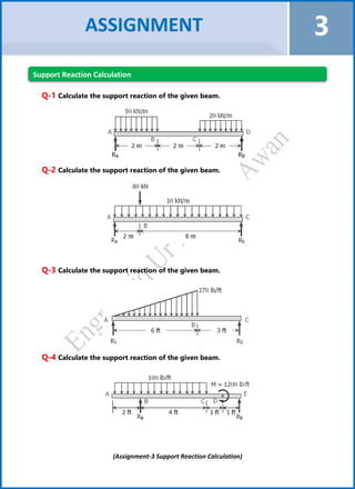
- 2. (Assignment-3 Support Reaction Calculation) Q-1 Calculate the support reaction of the given beam. Q-2 Calculate the support reaction of the given beam. Q-3 Calculate the support reaction of the given beam. Q-4 Calculate the support reaction of the given beam. ASSIGNMENT 3 Support Reaction Calculation
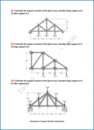
- 3. (Assignment-3 Support Reaction Calculation) Q-5 Calculate the support reaction of the given truss. Consider hinge support at A & roller support at E. Q-6 Calculate the support reaction of the given truss. Consider roller support at A & hinge support at E. Q-6 Calculate the support reaction of the given truss. Consider hinge support at A & roller support at E.
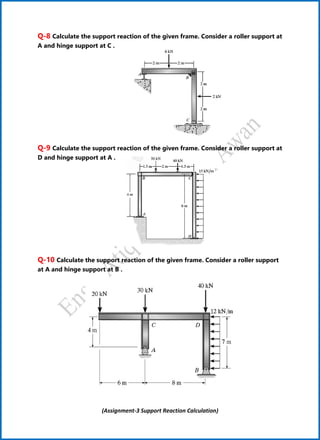
- 4. (Assignment-3 Support Reaction Calculation) Q-8 Calculate the support reaction of the given frame. Consider a roller support at A and hinge support at C . Q-9 Calculate the support reaction of the given frame. Consider a roller support at D and hinge support at A . Q-10 Calculate the support reaction of the given frame. Consider a roller support at A and hinge support at B .