1 of 14


Recommended
Impact of Free Jets
Impact of Free JetsMalla Reddy University
╠²
This document discusses the impact of free jets on stationary and moving plates and vanes. It explains the impulse-momentum principle and how it is used to calculate the hydrodynamic force exerted by a jet on plates and vanes in different configurations, including stationary/moving, flat/curved, vertical/inclined. Formulas are provided for calculating the forces and determining efficiencies. Applications to radial flow turbines like the Pelton wheel are described through concepts like angular momentum. The layout of typical hydropower installations and different efficiencies of turbines are also summarized.Force exerted by a jet on moving plates copy
Force exerted by a jet on moving plates copyAmitkumar7087
╠²
This document discusses the force exerted by a jet of water on stationary curved plates in different configurations. It examines when the jet strikes the curved plate at the center, when it strikes one end tangentially for a symmetrical plate, and when it strikes one end tangentially for an unsymmetrical plate. The force is calculated using equations that consider the mass flow rate, initial and final velocity components, and angle of deflection. Examples and solutions are provided.Mechanical Engineering-Fluid mechanics-impact of jets
Mechanical Engineering-Fluid mechanics-impact of jetsHimanshu Vasistha
╠²
PDF on topic of Impact of Jets from Subject of Fluid Mechanics. Next PDF will have topics when jets strike a moving plate/vane.Impact of jets
Impact of jetsAdhil Fuad Fuad
╠²
This document discusses the forces exerted on plates from a water jet in different configurations. It examines the forces when the plate is stationary and normal to the jet, inclined to the jet, curved at the center of the jet, curved with the jet striking tangentially at one end, and for a series of curved plates on a wheel. Key forces of Fx, Fy and the resultant force F are defined. Equations are provided for velocity components, momentum, torque, work done and efficiency.120218 chapter 8 momentum analysis of flow
120218 chapter 8 momentum analysis of flowBinu Karki
╠²
The document discusses momentum analysis of fluid flow. It contains the following key points:
1) The momentum equation is based on the law of conservation of momentum, which states that the net force acting on a fluid mass is equal to the rate of change of momentum of the fluid.
2) The momentum principle can be written as an impulse-momentum equation: the impulse of a force acting on a fluid mass over a short time interval is equal to the change in momentum of the fluid.
3) The momentum equation is used to determine the resultant force exerted by a flowing fluid on a pipe bend based on the fluid's velocity, pressure, area, and external forces at two sections of the pipe.Applied Hydraulics Module 3 Impact of Jets
Applied Hydraulics Module 3 Impact of Jetsnirannjan344
╠²
As per The Mumbai University Syllabus
MGMCET Kamothe Navi Mumbai
Prepared by
Asst.Prof. Niranjan Dilip PatilForce on Plate when Vane is moving in direction of jet | Fluid Power Engineering
Force on Plate when Vane is moving in direction of jet | Fluid Power EngineeringHarsh Lakhara
╠²
1. A jet of fluid exerts a force when it impinges on a plate or vane. The force depends on factors like the velocity and angle of the jet and plate as well as whether the plate is stationary or moving.
2. The impulse-momentum principle states that the force exerted by a jet equals the change in momentum of the fluid caused by the jet. This allows calculating the force as a function of the fluid's mass, velocities before and after impingement, and time of impingement.
3. Problems are presented calculating the force on plates in different configurations, such as stationary or moving plates that are vertical, inclined, or curved relative to the jet. Solutions involve considering theSteam turbine 
Steam turbine Preeda Prakotmak
╠²
The document discusses the principles of impulse and reaction steam turbines. It explains that impulse turbines use nozzles to convert steam pressure entirely into velocity before striking moving blades, while reaction turbines use both fixed and moving blades to gradually convert pressure to velocity. Compounding is also discussed as a way to achieve higher expansion ratios by dividing the expansion across multiple stages.Energy Audit -Types ,Instruments, reporting
Energy Audit -Types ,Instruments, reportingSudarshan Martande
╠²
Need of Energy Audit
Types of energy audit
Energy audit methodology
Instruments, equipment used in energy audit
Analysis and recommendations of energy audit
Benchmarking
Energy audit reporting
Introduction to software and simulation for energy auditing
Current Energy Conservation Act and Electricity Act and its featuresEnergy Scenario and Management , Energy audit and Management 
Energy Scenario and Management , Energy audit and Management Sudarshan Martande
╠²
Energy needs of a growing economy
Current and long-term energy scenario - India and World
Concept of energy conservation and energy efficiency
Energy and environment
Need of Renewable energy
Principles of Energy management
Energy policy
Energy action planning
Energy security and reliability
Energy sector reforms.
PROCESS PLANNING process parameter details
PROCESS PLANNING process parameter detailsSudarshan Martande
╠²
Introduction- methods of process planning,
drawing interpretation,
material evaluation,
steps in process selection,
production equipment and tooling selection,
process parameters calculation for various production processes,
Selection of jigs and fixtures,
selection of quality assurance methods,
documents for process planning,
Economics of process planning,
case studies.
JIGS-FIXTURES purpose of jigs & fixtures
JIGS-FIXTURES purpose of jigs & fixturesSudarshan Martande
╠²
Significance and purpose of jigs and fixtures and their functions in the manufacturing processes,
Concept of degree of freedom
3-2-1 principle of location.
General guidelines to design jigs and fixtures
advantages of jigs and fixtures.
Jigs-
Definition
Elements of jig with the types
Location guidelines
Principles of clamping
Principles of guiding
Channel jig, Template jig, Plate jig, Angle plate jig, Turn over jig, Box jig, Latch type jig.
Fixtures: Definition
Elements of fixtures
Location guidelines
Principles of clamping
Principles of setting element,
turning fixture
welding fixture
Milling fixture
Assembly and Inspection fixtures
Introduction to Mathematical Modeling. Optimization
Introduction to Mathematical Modeling. OptimizationSudarshan Martande
╠²
Introduction to Mathematical Modeling
Types of Modeling
Objective function
Constraints and Constraint surface
Mathematical modeling characteristics and limitations
Formulation of design problems
Introduction- methods of process planning,
drawing interpretation,
material evaluation,
steps in process selection,
production equipment and tooling selection,
process parameters calculation for various production processes,
Selection of jigs and fixtures,
selection of quality assurance methods,
documents for process planning,
Economics of process planning,
case studies.
PROCESS PLANNING. steps in process selection
PROCESS PLANNING. steps in process selectionSudarshan Martande
╠²
Introduction- methods of process planning, drawing interpretation, material evaluation, steps in process selection, production equipment and tooling selection, process parameters Selection of jigs and fixtures, selection of quality assurance methods, documents for process planning, case studies.Impact of Jet. Impulse momentum principle and its application to fixed and mo...
Impact of Jet. Impulse momentum principle and its application to fixed and mo...Sudarshan Martande
╠²
Introduction and Impact of Jet: Introduction to Turbomachines (Hydraulic & Thermal), Classification of Turbo machines, Applications of Turbomachines.
Impulse momentum principle and its application to fixed and moving flat, inclined, and curved plate/vanes. Velocity triangles and their analysis, work done equations, vane efficiencyIntroduction of Turbo Machines Hydraulic Turbines Introduction to Hydro pow...
Introduction of Turbo Machines Hydraulic Turbines Introduction to Hydro pow...Sudarshan Martande
╠²
Introduction and Impact of Jet
Introduction to Turbomachines (Hydraulic & Thermal), Classification of Turbo machines, Applications of Turbomachines. Impulse momentum principle and its application to fixed and moving flat, inclined, and curved plate/vanes. Velocity triangles and their analysis, work done equations, vane efficiency (No numerical)
Hydraulic Turbines
Introduction to Hydro power plant, Classification of Hydraulic Turbines, Concept of Impulse and Reaction Turbines. Construction, Principle of Working, design aspects, velocity diagrams and its analysis of Pelton wheel, Francis, and Kaplan turbines, Degree of reaction, Draft tube: types and efficiencies, governing of hydraulic turbines, Cavitation in turbines.
Theory of Metal Cutting Geometry of single-point cutting tool, Orthogonal and...
Theory of Metal Cutting Geometry of single-point cutting tool, Orthogonal and...Sudarshan Martande
╠²
Introduction to metal cutting, Elements of machining process, Geometry of single-point cutting tool, Orthogonal and Oblique cutting processes
Chip formation, Types of chips, Chip thickness ratio, Process parameters and their effect on machining, chip breakers
MerchantŌĆÖs Circle of forces analysis ŌĆō forces and energy calculations, power consumed ŌĆō MRR -Effect of Cutting variables on forces
Concepts of Machinability- Factors affecting machinability, Machinability Index, Tool Life, Tool life equation of Taylor, Tool wear and its types, Factors affecting on tool lifeGear _ Thread Manufacturing milling of gears (indexing methods and numerical)...
Gear _ Thread Manufacturing milling of gears (indexing methods and numerical)...Sudarshan Martande
╠²
Gear and Thread Manufacturing
Introduction, Materials of gears, Methods of gear manufacturing-casting, forging, forming etc, milling of gears Helical gear cutting, Gear Shaping and Gear hobbling, Gear inspection. Thread Manufacturing: Various methods of thread manufacturing, Grinding and Finishing processes mounting of grinding wheels Glazing and loa...
Grinding and Finishing processes mounting of grinding wheels Glazing and loa...Sudarshan Martande
╠²
Types and Operations of grinding machines
Grinding wheelŌĆō Shapes
Designation and selection Abrasives & classification
Bond & bonding
Grit
Grade & Structure of wheels
Types of grinding wheels
mounting of grinding wheels
Glazing and loading of wheels
Dressing and truing of wheels
Balancing of wheels
Diamond wheels
Super-finishing processes ŌĆō
Introduction to Honing, Lapping, Buffing and Burnishing. (Construction, working and controlling parameters)


AI, Tariffs and Supply Chains in Knowledge Graphs
AI, Tariffs and Supply Chains in Knowledge GraphsMax De Marzi
╠²
How tarrifs, supply chains and knowledge graphs combine.How to Build a Maze Solving Robot Using Arduino
How to Build a Maze Solving Robot Using ArduinoCircuitDigest
╠²
Learn how to make an Arduino-powered robot that can navigate mazes on its own using IR sensors and "Hand on the wall" algorithm.
This step-by-step guide will show you how to build your own maze-solving robot using Arduino UNO, three IR sensors, and basic components that you can easily find in your local electronics shop.Frankfurt University of Applied Science urkunde
Frankfurt University of Applied Science urkundeLisa Emerson
╠²
Duplicate Frankfurt University of Applied Science urkunde, make a Frankfurt UAS degree.US Patented ReGenX Generator, ReGen-X Quatum Motor EV Regenerative Accelerati...
US Patented ReGenX Generator, ReGen-X Quatum Motor EV Regenerative Accelerati...Thane Heins NOBEL PRIZE WINNING ENERGY RESEARCHER
╠²
Preface: The ReGenX Generator innovation operates with a US Patented Frequency Dependent Load Current Delay which delays the creation and storage of created Electromagnetic Field Energy around the exterior of the generator coil. The result is the created and Time Delayed Electromagnetic Field Energy performs any magnitude of Positive Electro-Mechanical Work at infinite efficiency on the generator's Rotating Magnetic Field, increasing its Kinetic Energy and increasing the Kinetic Energy of an EV or ICE Vehicle to any magnitude without requiring any Externally Supplied Input Energy. In Electricity Generation applications the ReGenX Generator innovation now allows all electricity to be generated at infinite efficiency requiring zero Input Energy, zero Input Energy Cost, while producing zero Greenhouse Gas Emissions, zero Air Pollution and zero Nuclear Waste during the Electricity Generation Phase. In Electric Motor operation the ReGen-X Quantum Motor now allows any magnitude of Work to be performed with zero Electric Input Energy.
Demonstration Protocol: The demonstration protocol involves three prototypes;
1. Protytpe #1, demonstrates the ReGenX Generator's Load Current Time Delay when compared to the instantaneous Load Current Sine Wave for a Conventional Generator Coil.
2. In the Conventional Faraday Generator operation the created Electromagnetic Field Energy performs Negative Work at infinite efficiency and it reduces the Kinetic Energy of the system.
3. The Magnitude of the Negative Work / System Kinetic Energy Reduction (in Joules) is equal to the Magnitude of the created Electromagnetic Field Energy (also in Joules).
4. When the Conventional Faraday Generator is placed On-Load, Negative Work is performed and the speed of the system decreases according to Lenz's Law of Induction.
5. In order to maintain the System Speed and the Electric Power magnitude to the Loads, additional Input Power must be supplied to the Prime Mover and additional Mechanical Input Power must be supplied to the Generator's Drive Shaft.
6. For example, if 100 Watts of Electric Power is delivered to the Load by the Faraday Generator, an additional >100 Watts of Mechanical Input Power must be supplied to the Generator's Drive Shaft by the Prime Mover.
7. If 1 MW of Electric Power is delivered to the Load by the Faraday Generator, an additional >1 MW Watts of Mechanical Input Power must be supplied to the Generator's Drive Shaft by the Prime Mover.
8. Generally speaking the ratio is 2 Watts of Mechanical Input Power to every 1 Watt of Electric Output Power generated.
9. The increase in Drive Shaft Mechanical Input Power is provided by the Prime Mover and the Input Energy Source which powers the Prime Mover.
10. In the Heins ReGenX Generator operation the created and Time Delayed Electromagnetic Field Energy performs Positive Work at infinite efficiency and it increases the Kinetic Energy of the system.Unit II: Design of Static Equipment Foundations
Unit II: Design of Static Equipment FoundationsSanjivani College of Engineering, Kopargaon
╠²
Design of Static Equipment, that is vertical vessels foundation.Wireless-Charger presentation for seminar .pdf
Wireless-Charger presentation for seminar .pdfAbhinandanMishra30
╠²
Wireless technology used in chargerUS Patented ReGenX Generator, ReGen-X Quatum Motor EV Regenerative Accelerati...
US Patented ReGenX Generator, ReGen-X Quatum Motor EV Regenerative Accelerati...Thane Heins NOBEL PRIZE WINNING ENERGY RESEARCHER
╠²
Preface: The ReGenX Generator innovation operates with a US Patented Frequency Dependent Load
Current Delay which delays the creation and storage of created Electromagnetic Field Energy around
the exterior of the generator coil. The result is the created and Time Delayed Electromagnetic Field
Energy performs any magnitude of Positive Electro-Mechanical Work at infinite efficiency on the
generator's Rotating Magnetic Field, increasing its Kinetic Energy and increasing the Kinetic Energy of
an EV or ICE Vehicle to any magnitude without requiring any Externally Supplied Input Energy. In
Electricity Generation applications the ReGenX Generator innovation now allows all electricity to be
generated at infinite efficiency requiring zero Input Energy, zero Input Energy Cost, while producing
zero Greenhouse Gas Emissions, zero Air Pollution and zero Nuclear Waste during the Electricity
Generation Phase. In Electric Motor operation the ReGen-X Quantum Motor now allows any
magnitude of Work to be performed with zero Electric Input Energy.
Demonstration Protocol: The demonstration protocol involves three prototypes;
1. Protytpe #1, demonstrates the ReGenX Generator's Load Current Time Delay when compared
to the instantaneous Load Current Sine Wave for a Conventional Generator Coil.
2. In the Conventional Faraday Generator operation the created Electromagnetic Field Energy
performs Negative Work at infinite efficiency and it reduces the Kinetic Energy of the system.
3. The Magnitude of the Negative Work / System Kinetic Energy Reduction (in Joules) is equal to
the Magnitude of the created Electromagnetic Field Energy (also in Joules).
4. When the Conventional Faraday Generator is placed On-Load, Negative Work is performed and
the speed of the system decreases according to Lenz's Law of Induction.
5. In order to maintain the System Speed and the Electric Power magnitude to the Loads,
additional Input Power must be supplied to the Prime Mover and additional Mechanical Input
Power must be supplied to the Generator's Drive Shaft.
6. For example, if 100 Watts of Electric Power is delivered to the Load by the Faraday Generator,
an additional >100 Watts of Mechanical Input Power must be supplied to the Generator's Drive
Shaft by the Prime Mover.
7. If 1 MW of Electric Power is delivered to the Load by the Faraday Generator, an additional >1
MW Watts of Mechanical Input Power must be supplied to the Generator's Drive Shaft by the
Prime Mover.
8. Generally speaking the ratio is 2 Watts of Mechanical Input Power to every 1 Watt of Electric
Output Power generated.
9. The increase in Drive Shaft Mechanical Input Power is provided by the Prime Mover and the
Input Energy Source which powers the Prime Mover.
10. In the Heins ReGenX Generator operation the created and Time Delayed Electromagnetic Field
Energy performs Positive Work at infinite efficiency and it increases the Kinetic Energy of the
system.

More Related Content
More from Sudarshan Martande (11)
Energy Audit -Types ,Instruments, reporting
Energy Audit -Types ,Instruments, reportingSudarshan Martande
╠²
Need of Energy Audit
Types of energy audit
Energy audit methodology
Instruments, equipment used in energy audit
Analysis and recommendations of energy audit
Benchmarking
Energy audit reporting
Introduction to software and simulation for energy auditing
Current Energy Conservation Act and Electricity Act and its featuresEnergy Scenario and Management , Energy audit and Management
Energy Scenario and Management , Energy audit and Management Sudarshan Martande
╠²
Energy needs of a growing economy
Current and long-term energy scenario - India and World
Concept of energy conservation and energy efficiency
Energy and environment
Need of Renewable energy
Principles of Energy management
Energy policy
Energy action planning
Energy security and reliability
Energy sector reforms.
PROCESS PLANNING process parameter details
PROCESS PLANNING process parameter detailsSudarshan Martande
╠²
Introduction- methods of process planning,
drawing interpretation,
material evaluation,
steps in process selection,
production equipment and tooling selection,
process parameters calculation for various production processes,
Selection of jigs and fixtures,
selection of quality assurance methods,
documents for process planning,
Economics of process planning,
case studies.
JIGS-FIXTURES purpose of jigs & fixtures
JIGS-FIXTURES purpose of jigs & fixturesSudarshan Martande
╠²
Significance and purpose of jigs and fixtures and their functions in the manufacturing processes,
Concept of degree of freedom
3-2-1 principle of location.
General guidelines to design jigs and fixtures
advantages of jigs and fixtures.
Jigs-
Definition
Elements of jig with the types
Location guidelines
Principles of clamping
Principles of guiding
Channel jig, Template jig, Plate jig, Angle plate jig, Turn over jig, Box jig, Latch type jig.
Fixtures: Definition
Elements of fixtures
Location guidelines
Principles of clamping
Principles of setting element,
turning fixture
welding fixture
Milling fixture
Assembly and Inspection fixtures
Introduction to Mathematical Modeling. Optimization
Introduction to Mathematical Modeling. OptimizationSudarshan Martande
╠²
Introduction to Mathematical Modeling
Types of Modeling
Objective function
Constraints and Constraint surface
Mathematical modeling characteristics and limitations
Formulation of design problems
Introduction- methods of process planning,
drawing interpretation,
material evaluation,
steps in process selection,
production equipment and tooling selection,
process parameters calculation for various production processes,
Selection of jigs and fixtures,
selection of quality assurance methods,
documents for process planning,
Economics of process planning,
case studies.
PROCESS PLANNING. steps in process selection
PROCESS PLANNING. steps in process selectionSudarshan Martande
╠²
Introduction- methods of process planning, drawing interpretation, material evaluation, steps in process selection, production equipment and tooling selection, process parameters Selection of jigs and fixtures, selection of quality assurance methods, documents for process planning, case studies.Impact of Jet. Impulse momentum principle and its application to fixed and mo...
Impact of Jet. Impulse momentum principle and its application to fixed and mo...Sudarshan Martande
╠²
Introduction and Impact of Jet: Introduction to Turbomachines (Hydraulic & Thermal), Classification of Turbo machines, Applications of Turbomachines.
Impulse momentum principle and its application to fixed and moving flat, inclined, and curved plate/vanes. Velocity triangles and their analysis, work done equations, vane efficiencyIntroduction of Turbo Machines Hydraulic Turbines Introduction to Hydro pow...
Introduction of Turbo Machines Hydraulic Turbines Introduction to Hydro pow...Sudarshan Martande
╠²
Introduction and Impact of Jet
Introduction to Turbomachines (Hydraulic & Thermal), Classification of Turbo machines, Applications of Turbomachines. Impulse momentum principle and its application to fixed and moving flat, inclined, and curved plate/vanes. Velocity triangles and their analysis, work done equations, vane efficiency (No numerical)
Hydraulic Turbines
Introduction to Hydro power plant, Classification of Hydraulic Turbines, Concept of Impulse and Reaction Turbines. Construction, Principle of Working, design aspects, velocity diagrams and its analysis of Pelton wheel, Francis, and Kaplan turbines, Degree of reaction, Draft tube: types and efficiencies, governing of hydraulic turbines, Cavitation in turbines.
Theory of Metal Cutting Geometry of single-point cutting tool, Orthogonal and...
Theory of Metal Cutting Geometry of single-point cutting tool, Orthogonal and...Sudarshan Martande
╠²
Introduction to metal cutting, Elements of machining process, Geometry of single-point cutting tool, Orthogonal and Oblique cutting processes
Chip formation, Types of chips, Chip thickness ratio, Process parameters and their effect on machining, chip breakers
MerchantŌĆÖs Circle of forces analysis ŌĆō forces and energy calculations, power consumed ŌĆō MRR -Effect of Cutting variables on forces
Concepts of Machinability- Factors affecting machinability, Machinability Index, Tool Life, Tool life equation of Taylor, Tool wear and its types, Factors affecting on tool lifeGear _ Thread Manufacturing milling of gears (indexing methods and numerical)...
Gear _ Thread Manufacturing milling of gears (indexing methods and numerical)...Sudarshan Martande
╠²
Gear and Thread Manufacturing
Introduction, Materials of gears, Methods of gear manufacturing-casting, forging, forming etc, milling of gears Helical gear cutting, Gear Shaping and Gear hobbling, Gear inspection. Thread Manufacturing: Various methods of thread manufacturing, Grinding and Finishing processes mounting of grinding wheels Glazing and loa...
Grinding and Finishing processes mounting of grinding wheels Glazing and loa...Sudarshan Martande
╠²
Types and Operations of grinding machines
Grinding wheelŌĆō Shapes
Designation and selection Abrasives & classification
Bond & bonding
Grit
Grade & Structure of wheels
Types of grinding wheels
mounting of grinding wheels
Glazing and loading of wheels
Dressing and truing of wheels
Balancing of wheels
Diamond wheels
Super-finishing processes ŌĆō
Introduction to Honing, Lapping, Buffing and Burnishing. (Construction, working and controlling parameters)
Impact of Jet. Impulse momentum principle and its application to fixed and mo...
Impact of Jet. Impulse momentum principle and its application to fixed and mo...Sudarshan Martande
╠²
Theory of Metal Cutting Geometry of single-point cutting tool, Orthogonal and...
Theory of Metal Cutting Geometry of single-point cutting tool, Orthogonal and...Sudarshan Martande
╠²
Gear _ Thread Manufacturing milling of gears (indexing methods and numerical)...
Gear _ Thread Manufacturing milling of gears (indexing methods and numerical)...Sudarshan Martande
╠²
Recently uploaded (20)
AI, Tariffs and Supply Chains in Knowledge Graphs
AI, Tariffs and Supply Chains in Knowledge GraphsMax De Marzi
╠²
How tarrifs, supply chains and knowledge graphs combine.How to Build a Maze Solving Robot Using Arduino
How to Build a Maze Solving Robot Using ArduinoCircuitDigest
╠²
Learn how to make an Arduino-powered robot that can navigate mazes on its own using IR sensors and "Hand on the wall" algorithm.
This step-by-step guide will show you how to build your own maze-solving robot using Arduino UNO, three IR sensors, and basic components that you can easily find in your local electronics shop.Frankfurt University of Applied Science urkunde
Frankfurt University of Applied Science urkundeLisa Emerson
╠²
Duplicate Frankfurt University of Applied Science urkunde, make a Frankfurt UAS degree.US Patented ReGenX Generator, ReGen-X Quatum Motor EV Regenerative Accelerati...
US Patented ReGenX Generator, ReGen-X Quatum Motor EV Regenerative Accelerati...Thane Heins NOBEL PRIZE WINNING ENERGY RESEARCHER
╠²
Preface: The ReGenX Generator innovation operates with a US Patented Frequency Dependent Load Current Delay which delays the creation and storage of created Electromagnetic Field Energy around the exterior of the generator coil. The result is the created and Time Delayed Electromagnetic Field Energy performs any magnitude of Positive Electro-Mechanical Work at infinite efficiency on the generator's Rotating Magnetic Field, increasing its Kinetic Energy and increasing the Kinetic Energy of an EV or ICE Vehicle to any magnitude without requiring any Externally Supplied Input Energy. In Electricity Generation applications the ReGenX Generator innovation now allows all electricity to be generated at infinite efficiency requiring zero Input Energy, zero Input Energy Cost, while producing zero Greenhouse Gas Emissions, zero Air Pollution and zero Nuclear Waste during the Electricity Generation Phase. In Electric Motor operation the ReGen-X Quantum Motor now allows any magnitude of Work to be performed with zero Electric Input Energy.
Demonstration Protocol: The demonstration protocol involves three prototypes;
1. Protytpe #1, demonstrates the ReGenX Generator's Load Current Time Delay when compared to the instantaneous Load Current Sine Wave for a Conventional Generator Coil.
2. In the Conventional Faraday Generator operation the created Electromagnetic Field Energy performs Negative Work at infinite efficiency and it reduces the Kinetic Energy of the system.
3. The Magnitude of the Negative Work / System Kinetic Energy Reduction (in Joules) is equal to the Magnitude of the created Electromagnetic Field Energy (also in Joules).
4. When the Conventional Faraday Generator is placed On-Load, Negative Work is performed and the speed of the system decreases according to Lenz's Law of Induction.
5. In order to maintain the System Speed and the Electric Power magnitude to the Loads, additional Input Power must be supplied to the Prime Mover and additional Mechanical Input Power must be supplied to the Generator's Drive Shaft.
6. For example, if 100 Watts of Electric Power is delivered to the Load by the Faraday Generator, an additional >100 Watts of Mechanical Input Power must be supplied to the Generator's Drive Shaft by the Prime Mover.
7. If 1 MW of Electric Power is delivered to the Load by the Faraday Generator, an additional >1 MW Watts of Mechanical Input Power must be supplied to the Generator's Drive Shaft by the Prime Mover.
8. Generally speaking the ratio is 2 Watts of Mechanical Input Power to every 1 Watt of Electric Output Power generated.
9. The increase in Drive Shaft Mechanical Input Power is provided by the Prime Mover and the Input Energy Source which powers the Prime Mover.
10. In the Heins ReGenX Generator operation the created and Time Delayed Electromagnetic Field Energy performs Positive Work at infinite efficiency and it increases the Kinetic Energy of the system.Unit II: Design of Static Equipment Foundations
Unit II: Design of Static Equipment FoundationsSanjivani College of Engineering, Kopargaon
╠²
Design of Static Equipment, that is vertical vessels foundation.Wireless-Charger presentation for seminar .pdf
Wireless-Charger presentation for seminar .pdfAbhinandanMishra30
╠²
Wireless technology used in chargerUS Patented ReGenX Generator, ReGen-X Quatum Motor EV Regenerative Accelerati...
US Patented ReGenX Generator, ReGen-X Quatum Motor EV Regenerative Accelerati...Thane Heins NOBEL PRIZE WINNING ENERGY RESEARCHER
╠²
Preface: The ReGenX Generator innovation operates with a US Patented Frequency Dependent Load
Current Delay which delays the creation and storage of created Electromagnetic Field Energy around
the exterior of the generator coil. The result is the created and Time Delayed Electromagnetic Field
Energy performs any magnitude of Positive Electro-Mechanical Work at infinite efficiency on the
generator's Rotating Magnetic Field, increasing its Kinetic Energy and increasing the Kinetic Energy of
an EV or ICE Vehicle to any magnitude without requiring any Externally Supplied Input Energy. In
Electricity Generation applications the ReGenX Generator innovation now allows all electricity to be
generated at infinite efficiency requiring zero Input Energy, zero Input Energy Cost, while producing
zero Greenhouse Gas Emissions, zero Air Pollution and zero Nuclear Waste during the Electricity
Generation Phase. In Electric Motor operation the ReGen-X Quantum Motor now allows any
magnitude of Work to be performed with zero Electric Input Energy.
Demonstration Protocol: The demonstration protocol involves three prototypes;
1. Protytpe #1, demonstrates the ReGenX Generator's Load Current Time Delay when compared
to the instantaneous Load Current Sine Wave for a Conventional Generator Coil.
2. In the Conventional Faraday Generator operation the created Electromagnetic Field Energy
performs Negative Work at infinite efficiency and it reduces the Kinetic Energy of the system.
3. The Magnitude of the Negative Work / System Kinetic Energy Reduction (in Joules) is equal to
the Magnitude of the created Electromagnetic Field Energy (also in Joules).
4. When the Conventional Faraday Generator is placed On-Load, Negative Work is performed and
the speed of the system decreases according to Lenz's Law of Induction.
5. In order to maintain the System Speed and the Electric Power magnitude to the Loads,
additional Input Power must be supplied to the Prime Mover and additional Mechanical Input
Power must be supplied to the Generator's Drive Shaft.
6. For example, if 100 Watts of Electric Power is delivered to the Load by the Faraday Generator,
an additional >100 Watts of Mechanical Input Power must be supplied to the Generator's Drive
Shaft by the Prime Mover.
7. If 1 MW of Electric Power is delivered to the Load by the Faraday Generator, an additional >1
MW Watts of Mechanical Input Power must be supplied to the Generator's Drive Shaft by the
Prime Mover.
8. Generally speaking the ratio is 2 Watts of Mechanical Input Power to every 1 Watt of Electric
Output Power generated.
9. The increase in Drive Shaft Mechanical Input Power is provided by the Prime Mover and the
Input Energy Source which powers the Prime Mover.
10. In the Heins ReGenX Generator operation the created and Time Delayed Electromagnetic Field
Energy performs Positive Work at infinite efficiency and it increases the Kinetic Energy of the
system.
Multi objective genetic approach with Ranking
Multi objective genetic approach with Rankingnamisha18
╠²
Multi objective genetic approach with Ranking 

Gauges are a Pump's Best Friend - Troubleshooting and Operations - v.07
Gauges are a Pump's Best Friend - Troubleshooting and Operations - v.07Brian Gongol
╠²
No reputable doctor would try to conduct a basic physical exam without the help of a stethoscope. That's because the stethoscope is the best tool for gaining a basic "look" inside the key systems of the human body. Gauges perform a similar function for pumping systems, allowing technicians to "see" inside the pump without having to break anything open. Knowing what to do with the information gained takes practice and systemic thinking. This is a primer in how to do that.google_developer_group_ramdeobaba_university_EXPLORE_PPT
google_developer_group_ramdeobaba_university_EXPLORE_PPTJayeshShete1
╠²
EXPLORE 6 EXCITING DOMAINS:
1. Machine Learning: Discover the world of AI and ML!
2. App Development: Build innovative mobile apps!
3. Competitive Programming: Enhance your coding skills!
4. Web Development: Create stunning web applications!
5. Blockchain: Uncover the power of decentralized tech!
6. Cloud Computing: Explore the world of cloud infrastructure!
Join us to unravel the unexplored, network with like-minded individuals, and dive into the world of tech!autonomous vehicle project for engineering.pdf
autonomous vehicle project for engineering.pdfJyotiLohar6
╠²
autonomous vehicle project for engineeringdecarbonization steel industry rev1.pptx
decarbonization steel industry rev1.pptxgonzalezolabarriaped
╠²
Webinar Decarbonization steel industryBest KNow Hydrogen Fuel Production in the World The cost in USD kwh for H2
Best KNow Hydrogen Fuel Production in the World The cost in USD kwh for H2Daniel Donatelli
╠²
The cost in USD/kwh for H2
Daniel Donatelli
Secure Supplies Group
Index
ŌĆó Introduction - Page 3
ŌĆó The Need for Hydrogen Fueling - Page 5
ŌĆó Pure H2 Fueling Technology - Page 7
ŌĆó Blend Gas Fueling: A Transition Strategy - Page 10
ŌĆó Performance Metrics: H2 vs. Fossil Fuels - Page 12
ŌĆó Cost Analysis and Economic Viability - Page 15
ŌĆó Innovations Driving Leadership - Page 18
ŌĆó Laminar Flame Speed Adjustment
ŌĆó Heat Management Systems
ŌĆó The Donatelli Cycle
ŌĆó Non-Carnot Cycle Applications
ŌĆó Case Studies and Real-World Applications - Page 22
ŌĆó Conclusion: Secure SuppliesŌĆÖ Leadership in Hydrogen Fueling - Page 27
Engineering at Lovely Professional University (LPU).pdf
Engineering at Lovely Professional University (LPU).pdfSona
╠²
LPUŌĆÖs engineering programs provide students with the skills and knowledge to excel in the rapidly evolving tech industry, ensuring a bright and successful future. With world-class infrastructure, top-tier placements, and global exposure, LPU stands as a premier destination for aspiring engineers.US Patented ReGenX Generator, ReGen-X Quatum Motor EV Regenerative Accelerati...
US Patented ReGenX Generator, ReGen-X Quatum Motor EV Regenerative Accelerati...Thane Heins NOBEL PRIZE WINNING ENERGY RESEARCHER
╠²
US Patented ReGenX Generator, ReGen-X Quatum Motor EV Regenerative Accelerati...
US Patented ReGenX Generator, ReGen-X Quatum Motor EV Regenerative Accelerati...Thane Heins NOBEL PRIZE WINNING ENERGY RESEARCHER
╠²
Unit 1-2 Impact of Jet diagram Turbo Machines
- 1. Unit ŌĆō I: Introduction to Turbo Machinery Impact of Jet Impulse momentum principle and its applications, Force exerted on fixed and moving flat plate, hinged plate, curved vanes, series of flat plates and radial vanes, velocity triangles and their analysis, work done equations, vane efficiency.
- 2. Force exerted by jet on plate
- 3. Force exerted on stationary plate held normal to jet. V1 = V V2= 0
- 4. Force exerted on moving plate held normal to jet. V1 = (V ŌĆōu) or V-U V2= 0
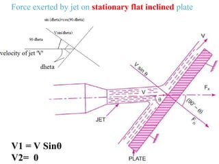
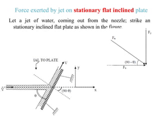
- 5. Force exerted by jet on stationary flat inclined plate V1 = V Sin╬Ė V2= 0
- 6. Force exerted by jet on stationary flat inclined plate Let a jet of water, coming out from the nozzle; strike an stationary inclined flat plate as shown in the figure.
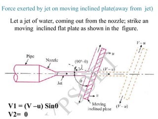
- 7. Force exerted by jet on moving inclined plate(away from jet) Let a jet of water, coming out from the nozzle; strike an moving inclined flat plate as shown in the figure. V1 = (V ŌĆōu) Sin╬Ė V2= 0
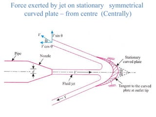
- 8. Force exerted by jet on stationary symmetrical curved plate ŌĆō from centre (Centrally)
- 9. Force exerted by jet on moving symmetrical curved plate -Centrally
- 10. Force exerted by jet on stationary curved plate from one end of plate ŌĆō symmetrical plate consider a water jet striking on symmetrical curved plate tangentially at one end as shown in fig V1 can be V1x & V1y V1x = Vcos ╬Ė V1y = Vsin ╬Ė V2 can be V2x & V2y V2x = - Vcos ╬Ė V2y = Vsin ╬Ė
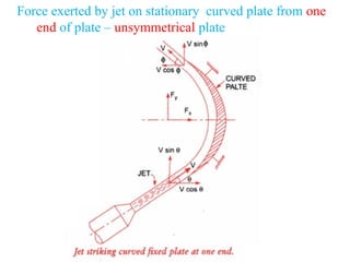
- 11. Force exerted by jet on stationary curved plate from one end of plate ŌĆō unsymmetrical plate
- 12. Force exerted by a jet of water on an unsymmetrical moving curved plate when jet strikes tangentially at one of the tips
- 14. Force exerted by a jet of water on a series of flat vanes