The document discusses synchronous and asynchronous counters and registers. It begins with an introduction to counters and describes asynchronous ripple counters and how to construct counters with modulus less than 2^n. It then covers asynchronous down counters, cascading counters, and synchronous parallel counters. Finally, it discusses registers including shift registers and their applications.
The document discusses synchronous and asynchronous counters and registers. It begins by introducing counters and describing asynchronous (ripple) counters. Examples of 2-bit and 3-bit ripple binary counters are provided. It then discusses asynchronous counters with modulus less than 2n and decade counters. Synchronous (parallel) counters are introduced and examples of 2-bit and 3-bit synchronous binary counters are described. Finally, the document discusses cascading asynchronous counters to create higher modulus counters and using registers to implement sequential circuits.
Digital Logic Design (EEEg4302)
Chapter 7 : Counters
This chapter discusses different types of counters, including asynchronous (ripple) counters and synchronous counters. Asynchronous counters use a ripple effect where one flip-flop triggers the next. Synchronous counters use a common clock signal to trigger all flip-flops simultaneously. The chapter also covers up/down counters, which can count up or down based on control signals, and methods for designing synchronous counters through state diagrams and logic expressions.
The document summarizes different types of digital counters, including asynchronous counters, synchronous counters, ring counters, and Johnson counters. Asynchronous counters have each flip-flop triggered by the previous one, limiting speed, while synchronous counters trigger all flip-flops simultaneously using a common clock, increasing speed. Ring counters circulate a single '1' bit around the register. Johnson counters are like ring counters but with the inverted output of the last flip-flop connected to the first. Examples and applications of each type are provided.
1. The document discusses different types of registers, counters, and shift registers including their components, functions, and loading/shifting processes.
2. It also covers synchronous and asynchronous counters as well as ring and Johnson counters.
3. Finally, it discusses integrated circuits and different digital logic families including TTL, ECL, MOS, CMOS, and I2L.
This document discusses synchronous counters, including their operation, design process, and examples. It covers 2-bit and 3-bit synchronous binary counters, 4-bit synchronous binary and BCD decade counters, and their state sequences. It also discusses designing counters using D, T, JK, and SR flip-flops. Additional topics include up/down counters, cascading counters, decoding counter states, and applications such as clocks and parking garage controls.
This document discusses different types of counters including asynchronous (ripple) counters, synchronous counters, down counters, and shift-register counters. It provides examples of how to construct various counters using flip-flops and logic gates. It also covers decoding the output states of counters and issues that can arise from propagation delays in asynchronous counters.
Latches
Flip-Flops - SR, JK, D and T
Master Slave Flip Flops
Shift Registers
SISO, SIPO, PISO, PIPO and Universal
Binary Counters
Synchronous and asynchronous up/down counters
mod - N counter
Counters for random sequence
Johnson counter and Ring counter
This document discusses asynchronous and synchronous counters. It provides examples of MOD-4, MOD-8, and MOD-6 asynchronous up counters using D flip-flops. It explains how synchronous counters use a common clock signal for all flip-flops. Examples are given for designing MOD-4 and MOD-4 synchronous up and down counters using JK flip-flops. The document also discusses asynchronous counter ICs and provides examples of MOD counters greater than a power of 2, such as MOD-9 and MOD-10, using T flip-flops.
This document summarizes a student project on digital logic counters. It introduces counters and classifies them as either asynchronous or synchronous. Asynchronous counters use a ripple effect where each subsequent flip-flop is clocked by the previous one's output, while synchronous counters use a single global clock. It then discusses decade counters specifically, which count from 0 to 9 and reset, and provides the circuit diagram for a decade counter that uses NAND gates to clear the counter when the binary state reaches 10.
There are several types of counters that can be implemented using flip-flops and logic gates. Asynchronous/ripple counters use the output of one flip-flop as the clock input for the next flip-flop, resulting in the clock pulse "ripping" through the chain. Synchronous counters clock all flip-flops simultaneously using a single clock. Decade counters count to 10 before resetting. Shift register counters like ring counters and Johnson counters produce specific output sequences by feeding the output back as the input.
This document discusses different types of counters used in digital circuits. It defines a counter as a sequential circuit that cycles through a sequence of states in response to clock pulses. Binary counters count in binary and can count from 0 to 2n-1 with n flip-flops. Asynchronous counters have flip-flops that are not triggered simultaneously by a clock, while synchronous counters use a common clock for all flip-flops. Other counter types include ring counters, Johnson counters, and decade counters. The document provides examples of binary, asynchronous, and synchronous counters and discusses their applications in areas like timing sequences and addressing memory.
Counters:
Introduction, Asynchronous counter, Terms related to counters, IC-7493 (4-bit binary counter), Synchronous counter, Bushing, Type T-Design, Type JK Design, Presettable counter, IC-7490, IC 7492, Synchronous counter ICs, Analysis of counter circuits
This presentation is all about counters, focusing on synchronous and asynchronous counters. The unique feature is the incorporation of the circuit images generated from MULTISIM software imparting practical knowledge to the users.
This presentation is all about counters, focusing on asynchronous and synchronous counters. The unique feature is the incorporation of the circuit images generated from MULTI SIM software imparting practical knowledge to the users.
This presentation is all about counters, focusing on synchronous and asynchronous counters. The unique feature is the incorporation of the circuit images generated from MULTISIM software imparting practical knowledge to the users.
This document summarizes a presentation about digital counters. It discusses different types of counters including asynchronous and synchronous counters. Asynchronous counters have the clock pulse applied to the first flip-flop, while successive flip-flops are triggered by the output of the previous one, resulting in cumulative settling time. Synchronous counters have all flip-flop clock inputs connected together and triggered simultaneously by input pulses. The document provides truth tables and examples of asynchronous and synchronous counter circuit designs using JK flip-flops. It concludes with a thank you for the presentation.
This document discusses counters and their applications. It begins by defining a counter as a sequential digital device used for counting up or down. There are different types of counters including asynchronous (ripple) counters and binary counters. Counters are used for applications like frequency division and reducing the frequency of a clock signal. Flip-flops are also discussed as they are the basic building blocks of counters. Specific counter circuits like binary ripple counters, BCD counters, and techniques for designing counters with modular values other than powers of two are described.
This document discusses asynchronous and synchronous counters. It begins by explaining the basic concepts of asynchronous and synchronous counters, and the differences between them. It then provides details on asynchronous up counters, down counters, and up/down counters. Examples are given of MOD-4, MOD-8, and higher MOD asynchronous counters. Synchronous counters are introduced which allow all flip-flops to change simultaneously on the clock pulse. Examples are provided of decade counters and using integrated circuits like the 74293 for building asynchronous counters.
Presentation on Counters for (Digital Systems Design).pptxAniruddh70
油
1. Counters are sequential circuits that cycle through a sequence of states upon receiving a clock pulse or other input signal. They are used for applications like counting events, generating timing sequences, and addressing memory.
2. There are two main types of counters: asynchronous/ripple counters where each flip-flop is triggered by the previous one, and synchronous counters where all flip-flops are triggered simultaneously by a clock. Asynchronous counters are simpler but slower while synchronous counters are faster but more complex.
3. Binary counters follow a binary sequence and can count from 0 to 2n-1 for an n-bit counter. Other counter types include up/down, ring, Johnson, and decade counters.
This document discusses different types of counters. It begins by classifying counters as either asynchronous (ripple) or synchronous. It then describes binary, decimal, octal and special counters based on their counting sequences. The document provides examples of 3-bit asynchronous and synchronous up/down counters. It explains how to create divide-by-N counters using MOD-N ripple counters. BCD ripple counters and 3-decade decimal counters are also illustrated. Finally, the timing and operation of synchronous counters is examined along with synchronous down and up/down counters.
"Zen and the Art of Industrial Construction"
Once upon a time in Gujarat, Plinth and Roofs was working on a massive industrial shed project. Everything was going smoothlyblueprints were flawless, steel structures were rising, and even the cement was behaving. That is, until...
Meet Ramesh, the Stressed Engineer.
Ramesh was a perfectionist. He measured bolts with the precision of a Swiss watchmaker and treated every steel beam like his own child. But as the deadline approached, Rameshs stress levels skyrocketed.
One day, he called Parul, the total management & marketing mastermind.
Ramesh (panicking): "Parul maam! The roof isn't aligning by 0.2 degrees! This is a disaster!"
Parul (calmly): "Ramesh, have you tried... meditating?"
、 Ramesh: "Meditating? Maam, I have 500 workers on-site, and you want me to sit cross-legged and hum Om?"
Parul: "Exactly. Mystic of Seven can help!"
Reluctantly, Ramesh agreed to a 5-minute guided meditation session.
He closed his eyes.
鏝 He breathed deeply.
He chanted "Om Namah Roofaya" (his custom version of a mantra).
When he opened his eyes, a miracle happened!
ッ His mind was clear.
The roof magically aligned (okay, maybe the team just adjusted it while he was meditating).
And for the first time, Ramesh smiled instead of calculating load capacities in his head.
Lesson Learned: Sometimes, even in industrial construction, a little bit of mindfulness goes a long way.
From that day on, Plinth and Roofs introduced tea breaks with meditation sessions, and productivity skyrocketed!
Moral of the story: "When in doubt, breathe it out!"
#PlinthAndRoofs #MysticOfSeven #ZenConstruction #MindfulEngineering
Preface: The ReGenX Generator innovation operates with a US Patented Frequency Dependent Load Current Delay which delays the creation and storage of created Electromagnetic Field Energy around the exterior of the generator coil. The result is the created and Time Delayed Electromagnetic Field Energy performs any magnitude of Positive Electro-Mechanical Work at infinite efficiency on the generator's Rotating Magnetic Field, increasing its Kinetic Energy and increasing the Kinetic Energy of an EV or ICE Vehicle to any magnitude without requiring any Externally Supplied Input Energy. In Electricity Generation applications the ReGenX Generator innovation now allows all electricity to be generated at infinite efficiency requiring zero Input Energy, zero Input Energy Cost, while producing zero Greenhouse Gas Emissions, zero Air Pollution and zero Nuclear Waste during the Electricity Generation Phase. In Electric Motor operation the ReGen-X Quantum Motor now allows any magnitude of Work to be performed with zero Electric Input Energy.
Demonstration Protocol: The demonstration protocol involves three prototypes;
1. Protytpe #1, demonstrates the ReGenX Generator's Load Current Time Delay when compared to the instantaneous Load Current Sine Wave for a Conventional Generator Coil.
2. In the Conventional Faraday Generator operation the created Electromagnetic Field Energy performs Negative Work at infinite efficiency and it reduces the Kinetic Energy of the system.
3. The Magnitude of the Negative Work / System Kinetic Energy Reduction (in Joules) is equal to the Magnitude of the created Electromagnetic Field Energy (also in Joules).
4. When the Conventional Faraday Generator is placed On-Load, Negative Work is performed and the speed of the system decreases according to Lenz's Law of Induction.
5. In order to maintain the System Speed and the Electric Power magnitude to the Loads, additional Input Power must be supplied to the Prime Mover and additional Mechanical Input Power must be supplied to the Generator's Drive Shaft.
6. For example, if 100 Watts of Electric Power is delivered to the Load by the Faraday Generator, an additional >100 Watts of Mechanical Input Power must be supplied to the Generator's Drive Shaft by the Prime Mover.
7. If 1 MW of Electric Power is delivered to the Load by the Faraday Generator, an additional >1 MW Watts of Mechanical Input Power must be supplied to the Generator's Drive Shaft by the Prime Mover.
8. Generally speaking the ratio is 2 Watts of Mechanical Input Power to every 1 Watt of Electric Output Power generated.
9. The increase in Drive Shaft Mechanical Input Power is provided by the Prime Mover and the Input Energy Source which powers the Prime Mover.
10. In the Heins ReGenX Generator operation the created and Time Delayed Electromagnetic Field Energy performs Positive Work at infinite efficiency and it increases the Kinetic Energy of the system.
Welcome to the March 2025 issue of WIPAC Monthly the magazine brought to you by the LinkedIn Group WIPAC Monthly.
In this month's edition, on top of the month's news from the water industry we cover subjects from the intelligent use of wastewater networks, the use of machine learning in water quality as well as how, we as an industry, need to develop the skills base in developing areas such as Machine Learning and Artificial Intelligence.
Enjoy the latest edition
Lecture -3 Cold water supply system.pptxrabiaatif2
油
The presentation on Cold Water Supply explored the fundamental principles of water distribution in buildings. It covered sources of cold water, including municipal supply, wells, and rainwater harvesting. Key components such as storage tanks, pipes, valves, and pumps were discussed for efficient water delivery. Various distribution systems, including direct and indirect supply methods, were analyzed for residential and commercial applications. The presentation emphasized water quality, pressure regulation, and contamination prevention. Common issues like pipe corrosion, leaks, and pressure drops were addressed along with maintenance strategies. Diagrams and case studies illustrated system layouts and best practices for optimal performance.
Were excited to share our product profile, showcasing our expertise in Industrial Valves, Instrumentation, and Hydraulic & Pneumatic Solutions.
We also supply API-approved valves from globally trusted brands, ensuring top-notch quality and internationally certified solutions. Lets explore valuable business opportunities together!
We specialize in:
Industrial Valves (Gate, Globe, Ball, Butterfly, Check)
Instrumentation (Pressure Gauges, Transmitters, Flow Meters)
Pneumatic Products (Cylinders, Solenoid Valves, Fittings)
As authorized partners of trusted global brands, we deliver high-quality solutions tailored to meet your industrial needs with seamless support.
Optimization of Cumulative Energy, Exergy Consumption and Environmental Life ...J. Agricultural Machinery
油
Optimal use of resources, including energy, is one of the most important principles in modern and sustainable agricultural systems. Exergy analysis and life cycle assessment were used to study the efficient use of inputs, energy consumption reduction, and various environmental effects in the corn production system in Lorestan province, Iran. The required data were collected from farmers in Lorestan province using random sampling. The Cobb-Douglas equation and data envelopment analysis were utilized for modeling and optimizing cumulative energy and exergy consumption (CEnC and CExC) and devising strategies to mitigate the environmental impacts of corn production. The Cobb-Douglas equation results revealed that electricity, diesel fuel, and N-fertilizer were the major contributors to CExC in the corn production system. According to the Data Envelopment Analysis (DEA) results, the average efficiency of all farms in terms of CExC was 94.7% in the CCR model and 97.8% in the BCC model. Furthermore, the results indicated that there was excessive consumption of inputs, particularly potassium and phosphate fertilizers. By adopting more suitable methods based on DEA of efficient farmers, it was possible to save 6.47, 10.42, 7.40, 13.32, 31.29, 3.25, and 6.78% in the exergy consumption of diesel fuel, electricity, machinery, chemical fertilizers, biocides, seeds, and irrigation, respectively.
Engineering at Lovely Professional University (LPU).pdfSona
油
LPUs engineering programs provide students with the skills and knowledge to excel in the rapidly evolving tech industry, ensuring a bright and successful future. With world-class infrastructure, top-tier placements, and global exposure, LPU stands as a premier destination for aspiring engineers.
. マ留 裡留略龍侶: Foundation Analysis and Design: Single Piles
Welcome to this comprehensive presentation on "Foundation Analysis and Design," focusing on Single PilesStatic Capacity, Lateral Loads, and Pile/Pole Buckling. This presentation will explore the fundamental concepts, equations, and practical considerations for designing and analyzing pile foundations.
We'll examine different pile types, their characteristics, load transfer mechanisms, and the complex interactions between piles and surrounding soil. Throughout this presentation, we'll highlight key equations and methodologies for calculating pile capacities under various conditions.
2. CS1104-13 Lecture 13: Sequential Logic:
Counters and Registers
2
Sequential Logic
Counters and Registers
Registers
Introduction: Registers
Simple Registers
Registers with Parallel Load
Using Registers to implement Sequential Circuits
Shift Registers
Serial In/Serial Out Shift Registers
Serial In/Parallel Out Shift Registers
Parallel In/Serial Out Shift Registers
Parallel In/Parallel Out Shift Registers
3. CS1104-13 Introduction: Counters 3
Introduction: Counters
Counters are circuits that cycle through a specified
number of states.
Two types of counters:
synchronous (parallel) counters
asynchronous (ripple) counters
Ripple counters allow some flip-flop outputs to be
used as a source of clock for other flip-flops.
Synchronous counters apply the same clock to all
flip-flops.
6. CS1104-13 Asynchronous (Ripple) Counters 6
Asynchronous (Ripple) Counters
Asynchronous counters: the flip-flops do not change
states at exactly the same time as they do not have a
common clock pulse.
Also known as ripple counters, as the input clock
pulse ripples through the counter cumulative
delay is a drawback.
n flip-flops a MOD (modulus) 2n
counter. (Note: A
MOD-x counter cycles through x states.)
Output of the last flip-flop (MSB) divides the input
clock frequency by the MOD number of the counter,
hence a counter is also a frequency divider.
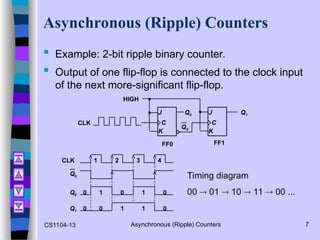
7. CS1104-13 Asynchronous (Ripple) Counters 7
Asynchronous (Ripple) Counters
Example: 2-bit ripple binary counter.
Output of one flip-flop is connected to the clock input
of the next more-significant flip-flop.
K
J
K
J
HIGH
Q0 Q1
Q0
FF1
FF0
CLK C
C
Timing diagram
00 01 10 11 00 ...
4
3
2
1
CLK
Q0
Q0
Q1
1 1
1 1
0
0 0
0 0
0
8. CS1104-13 Asynchronous (Ripple) Counters 8
Asynchronous (Ripple) Counters
Example: 3-bit ripple binary counter.
K
J
K
J
Q0 Q1
Q0
FF1
FF0
C
C
K
J
Q1
C
FF2
Q2
CLK
HIGH
4
3
2
1
CLK
Q0
Q1
1 1
1 1
0
0 0
0 0
0
8
7
6
5
1 1
0 0
1 1
0 0
Q2 0 0
0 0 1 1 1
1 0
Recycles back to 0
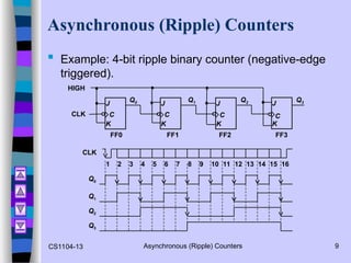
9. CS1104-13 Asynchronous (Ripple) Counters 9
Asynchronous (Ripple) Counters
Example: 4-bit ripple binary counter (negative-edge
triggered).
K
J
K
J
Q1
Q0
FF1
FF0
C
C
K
J
C
FF2
Q2
CLK
HIGH
K
J
C
FF3
Q3
CLK
1 2 3 4 5 6 7 8 9 10 11 12 13 14 15 16
Q0
Q1
Q2
Q3
10. CS1104-13 Synchronous (Parallel) Counters 10
Synchronous (Parallel) Counters
Synchronous (parallel) counters: the flip-flops are
clocked at the same time by a common clock pulse.
We can design these counters using the sequential
logic design process.