


![COUNTERS [Synchronous and Asynchronous]](https://cdn.slidesharecdn.com/ss_thumbnails/counters-211217083059-thumbnail.jpg?width=560&fit=bounds)


More Related Content
Similar to Counters_pptx.pptx (20)
Recently uploaded (20)


Counters_pptx.pptx
- 1. By : Rand Aqra & Ikhas Saleh Instructure : Dr. Ghassan Andoni 1 Counters
- 2. Contents 2 ï Introduction To Counters . ï Frequency Division . ï Flip Flops. ï Types of counters . ï Problems . ï Some Applications of counters . ï References .
- 3. 1. Introduction To Counters : 3 ï A counter is a sequential digital device, which is used for counting ( up or down) . Counters is a very wide application of flip-flops, where it is a group of flip- flops with a clock signal applied . ï Types of counters : o Asynchronous (Ripple) counters.
- 4. 4
- 5. 2. Frequency Division : âĒ Frequency division is one of the main propose of counters, the division process is used to reduce the frequency of the clock input waveform. 5
- 6. Divide by 2 counter : 6 ï This type of counters reduces the frequency of the clock input exactly to the half for each flip-flop, this type of counters is called binary ripple counters. For nth FFs , the input frequency reduces by the factor ððð 2ð . ï For example, the output frequency : ïAfter 4 FFs = ððð 24 = ððð 16 ï After 8 FFs = ððð 256 ïAfter 12 FFs = ððð 4096
- 7. 7
- 8. 8
- 9. Example : 9 ï If an input frequency of 200 KHz is applied to a binary ripple counter that has 6 FFs , what is the out put frequency of the last FF in KHz ? ï Solution : f= 200 26 = 3.125 KHz
- 10. 3. Flip Flops : 3.1 : JK Flip Flop : ïķ Remembe r : 10 âĒ The most versatile of the basic FFs. âĒ A FF with two data inputs J & K . âĒ If J and K are different then the output Q takes the value of J at the next clock edge. âĒ If J and K are both low then no change occurs. âĒ If J and K are both high then the output is complemented .
- 11. ïķ Truth Table : ïķ Remarks : ï§ To help remember the Reset mode you can think of ( K=1) means Kill the output . ï§ To help remember the Set mode you can think of ( J=1) means the output will Jump high. 11 J K Clk Q (t+1) 0 0 Q0 No change 0 1 0 Reset 1 0 1 set 1 1 Q Complement ïķCharacteristic Equation : Q(t+1) = JQ + KQ
- 13. Asynchronous inputs of JK FF : 13 ï The J and K inputs are called synchronous inputs of the JK FF. ï The JK FF have two asynchronous inputs : Preset and Clear . ï These are active low inputs. ï When the preset input is activated, the FF will be set (Q=1) regardless of any of the synchronous inputs or the clock. When the clear input is activated, the FF will be reset (Q=0), regardless of any of the synchronous inputs or the clock. Preset Clear FF response 1 1 Clocked operation 0 1 Q=1 1 0 Q=0 0 0 Not used
- 14. 14
- 15. 3.2 : D Flip Flop : 15 ï One data input D . ï The output Q follows D at the clock edge . ï It is useful for parallel data transfer. ï If D is high : set state. ï If D is low : Reset state. ïķ Remembe r :
- 16. ïķ Truth Table : 16 D Clk Q(t+1) 0 0 Reset 1 1 set ïķCharacteristic Equation : Q(t+1) = D
- 18. 4. Types of counters : 4.1 : Asynchronous (Ripple) Counter : 18 âĒ Definition : Type of counters in which each flip flop output serves as the clock input signal for the next FF in the sequence. âĒ In Asynchronous counters , the input of some or all FFs are triggered not by the common clock pulse, but rather by the transition that occurs in other FF output. âĒ The FFs donât change states at exactly the same time as they donât have a common clock pulse. âĒ For a ripple counter consists of n FFs , the number of its states equals 2n , and It can count from 0 to (2n -1). Notes : ï§ To operate the toggle mode , the FFs must be connected with J=K=1 ï§ Remember that the FFs are connected in series in Asynchronous
- 19. 19 ï Binary counter : Group of FFs connected in a special arrangement in which the states of FF represent the binary number equivalent to the number of pulses that have occurred at the input of the counter. ï Binary Ripple counter is called also, a Mod-X counter, where X is the number of counter states and its equal to 2n , for n FFs . ï The first FF in the counter is called LSB , and the last FF is called MSB. ï The output of MSB divides the input clock frequency by X 4.1.1: Binary Ripple Counter :
- 20. 20 ï The figure below shows a 4-bit binary counter (Mod- 16) : 1. The clock pulse applied only to the Clk input of flip flop A. 2. The input for each of the next FFs is the output of the previous FF. So the output of FF A is the input of FF B , the output of FF B is the input of FF C , and the output of FF C is the input of FF D. 3. FF A will toggle each time the clock pulse make a transition. 4. Since The output of FF A is the input of FF B ,FF B will toggle each time the output of FF A goes from 1 to 0 , and so on. A B C D
- 21. 21 5. This means only FF A responds to the clock pulses. FF B has to wait for FF A to change states before its toggled , and so on. 6. Thus, all FFs donât changes states in exact synchronism with the clock pulse. And because of that it is called asynchronous counters. 7. Because of the phenomenon we talked about in 5 , there is a delay between the response of sequential FFs. 8. So , this type of counters is also commonly called a ripple counter. (simply we can say that the input clock ripples through the counter.) 9. After 15 clock pulse , the counter has finished its first complete cycle (0000 through 1111), and in its 16 clock pulse it will recycle back to (0000) . Truth table for 4-bit binary counter Note : . A counter may count up or count down or count up and down depending on the input control.
- 22. 22 0 1 0 0 0 0 0 0 0 0 0 0 0 0 0 0 0 0 0 0 0 0 0 1 0 0 0 0 0 0 1 1 1 1 1 1 1 1 1 1 1 1 1 1 1 1 1 1 1 1 1 1 1 1 Timing diagram of a 4-bit binary ripple counter 1 1 1 1 1 1 0 0 0 0
- 23. 23 4-bit binary ripple counter using D FF 4-bit binary ripple counter using T FF
- 24. Example : A 2-bit binary counter (Mod-4) . 24 Truth table 2- bit binary ripple counter using JK FF State diagram
- 26. A 3-bit binary counter (Mod-8) . Example : 26 3- bit binary ripple counter using JK FF Timing diagram State diagram
- 27. 27 Propagation delays in 3-bit binary ripple counter Notes : - Cumulative propagation delay can cause problems at high frequencies. - If the period between input pulses is longer than the cumulative propagation delay of the counters, problems can be avoided. But, if the cumulative propagation delay is longer than the period between input pulses, some counter states may be misrepresented.
- 28. Asynchronous Counters with mod numbers < 2n : 28 ï In the previous slides we know how to design a binary ripple counters with mod number = 2n , where n equals the number of FFs. Like Mod-4 , Mod-8 , and Mod-16 . ï But , what about Mod-5 , Mod-6 or Mod-15 counters ? ï How we can design a counter with mod number â 2n ? ï By allowing the counter to skip states that are normally part of the counting sequence. The resulting sequence is called truncated sequence. Remark : To obtain the truncated sequence is necessary to force the counter to recycle before going through all of its possible states.
- 29. 29 ï One of the most common for obtain a truncated sequence is explained in the figure above , where a 3-bit binary counter connected to a NAND gate is shown. ï Without the NAND gate the counter is a 8-Mod binary counter, which will count from 000 through 111. ï The NAND gate will change the counter sequence as follows : 1. The NAND output is connected to the counter Clear inputs of each FF. 2. When the NAND output is high, it will have no effect on the counter. 3. When it goes low, it will clear all the FFs so that the counter All J&K inputs are 1
- 30. 30 4. The inputs of the NAND gate are the outputs of the B and C FFs. 5. So, the NAND output will go low whenever B=C=1. This condition will occur when the counter goes from 101 to 110. 6. The low at the NAND output will immediately clear the counter to the 000 state, and then it will goes back high, since the B=C=1 condition no longer exists. 7. Thus , we can say that this counter counts from 000 (0) to 101 (5) and then recycles to 000. 8. It is essentially skips 110 and 111 so that it goes through only six different states. 9. Thus , it is a Mod-6 counter. CB A 000 001 010 011 100 101 110 Temporary state needed to clear counter Truncated sequence Note : we say immediately but generally it recycles within a few nanoseconds
- 31. 31 ï The waveform at the B output contains a spike caused by the momentary occurrence of the 110 state before clearing. Mod-6 counter produced by clearing a Mod-8 counter when count of 6 (110) occu
- 32. 32 State transition diagram for the Mod-6 counter
- 33. General procedure to design a Mod-X counter ( or a X-bit binary ripple counter) : 33 1. Find the smallest number of FFs such that XâĪ 2n . 2. Connect them as a counter. â If X=2n , donât do steps 3 and 4 â. 3. Connect a NAND gate to the asynchronous Clear inputs of all the FFs. 4. Determine which FFs will be in high state at a count =X; then connect the normal outputs of these FFs to the NAND gate inputs.
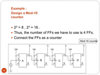
- 34. Example : Design a Mod-10 counter. 34 ï 23 = 8 , 24 = 16 . ï Thus, the number of FFs we have to use is 4 FFs. ï Connect the FFs as a counter D C B A Mod-16 counter
- 35. 35 ï Connect the NAND gate to the asynchronous Clear inputs of all FFs. ï Mod-10 counter will count from 0000 through 1001. ï So, it must be rest to 0000 state when the count of 1010 is reached. ï Therefore, FF outputs B and D must be connected as the NAND gate inputs. ï In other words , the NAND gate will go low when B=D=1 (1010 state), thin the low at NAND output will immediately clear the counter to 0000 state. Mod-10 counter DCB A 0000 0001 0010 0011 0100 0101 0110 0111 1000 1001 1010 C A B D
- 36. 36 State Diagram Mod-10 counter produced by clearing a Mod-16 counter when count of 10 (1001) occurs
- 37. 4.1.2: BCD Counters : 37 ïķ BCD counter : binary counter that counts from 0000 (0) to 1001 (9) before it recycles. And its called also a decade counter. ï A decade counter is any counter that has 10 distinct states . And any decade counter that counts in binary from 0000 to 1001 is a BCD counter. ï The Mod-10 counter , that we explained on the previous example, is a BCD decade counter. Note : BCD : Binary Coded Decimal
- 38. 38 BCD counter timing diagram
- 39. Display a BCD to 7-Segment Decoder / Driver : 39 ïķ BCD to 7-segment Decoder : Digital circuit that takes a 4-bit BCD input and activates the required outputs to display the equivalent decimal digit of a 7-segment display ï Base 10 numbers maybe displayed using 7 segment display , as we see in calculators and watches. ï The segments may be made of : the liquid crystal (LCD), or LED. ï The most common arrangement uses the LEDs for each segment. ï A BCD to 7-segments decoder is used to take a 4-bit BCD inputs and provide the outputs that will pass current through LEDs to display digit.
- 40. 40 D C B A a b c d e f g display 0 0 0 0 1 1 1 1 1 1 0 0 0 0 0 1 0 1 1 0 0 0 0 1 0 0 1 0 1 1 0 1 1 0 1 2 0 0 1 1 1 1 1 1 0 0 1 3 0 1 0 0 0 1 1 0 0 1 1 4 0 1 0 1 1 0 1 1 0 1 1 5 0 1 1 0 1 0 1 1 1 1 1 6 0 1 1 1 1 1 1 0 0 1 0 7 1 0 0 0 1 1 1 1 1 1 1 8 1 0 0 1 1 1 1 1 0 1 1 9 Truth Table for display BCD to 7-segment Decoder
- 41. 41 ï There is two types to display : 1. A common cathode display : The cathodes of all of all the segments is tied to each other and connected to ground. In this type the segment will turn on when its input is high. 2. A common anode display : The anodes of all the segments is tied to each other and connected to + Vcc. In this type the segment will turn if when its input is low.
- 42. 42
- 43. 4.1.3: Asynchronous Down Counters : ïķ Remark : Note that when the clK input of FFs is connected to negative edge , the inverted output (Q) of FF0 will be connected to the input clk input for the FF1 , and so on. While , as you see previously, on the up counters when the clK input of FFs is connected to negative edge , the output (Q) of FF0 will be connected to the input clk input for the FF1 43 ï The ripple down counters, will count downward from maximum count to 0. ï It works in the same method that the ripple up counters works. Mod-8 down ripple counte All J &K inputs are high Stat e CB A 7 111 6 110 5 101 4 100 3 011 2 010 1 001 0 000
- 44. 44 Mod-8 down ripple counter timing diagram Mod-8 down ripple counter state diagram
- 45. 4.1.4: Asynchronous Bidirectional Counters : 45 ï This counter designed to count in both directions up and down . ï It counts up or down depending on the status of the control signals UP and DOWN ï When the UP input is at 1 and the DOWN input is at 0, the NAND network between FF0 and FF1 will gate the non- inverted output (Q) of FF0 into the clock input of FF1, and so on for the next FFs. Thus the counter will count up. 3-bit bidirectional ripple counter
- 46. 46 ï When the UP input is at 0 and the DOWN input is at 1, the NAND network between FF0 and FF1 will gate the inverted output (Q) of FF0 into the clock input of FF1, and so on for the next FFs. Thus the counter will count down . Up states CBA Down states CBA 0 000 7 111 1 001 6 110 2 010 5 101 3 011 4 100 4 100 3 011 5 101 2 010 6 110 1 001 7 111 0 000 Count up mode Count down mode Note : The ripple up/down counter is slower than an up counter or a down counter because of the additional propagation delay introduced by the NAND networks.
- 47. 4.1.5 : Asynchronous Counters advantages and disadvantages: 47 ï Advantages : 1. Asynchronous Counters can easily be made from Toggle or D-type flip-flops. 2. They are called âAsynchronous Countersâ because the clock input of the flip-flops are not all driven by the same clock signal. 3. Each output in the chain depends on a change in state from the previous flip-flops output. 4. Asynchronous counters are sometimes called ripple counters because the data appears to ârippleâ from the output of one flip-flop to the input of the next. 5. They can be implemented using âdivide-by-nâ counter circuits. 6. Truncated counters can produce any modulus number count.
- 48. 48 ï Disadvantages : 1. An extra âre-synchronizingâ output flip-flop may be required. 2. To count a truncated sequence not equal to 2n, extra feedback logic is required. 3. Counting a large number of bits, propagation delay by successive stages may become undesirably large. 4. This delay gives them the nickname of âPropagation Countersâ. 5. Counting errors occur at high clocking frequencies. 6. Synchronous Counters are faster and more reliable as they use the same clock signal for all flip-flops.
- 49. 4.2 : Synchronous (Parallel) Counter : 49 ï We see that an asynchronous suffers from what is known as âPropagation Delayâ in which the timing signal is delayed a fraction through each flip-flop. ï All the individual output bits changing state at exactly the same time in response to the common clock signal with no ripple effect and therefore, no propagation delay.
- 50. 50 4.2.1 : synchronous binary counters :
- 51. 51 ï the external clock pulses are fed directly to each of the J-K flip flops in the counter chain and that both the J and K inputs are all tied together in toggle mode. ï but only in the first flip-flop, flip-flop FFA (LSB) are they connected HIGH, logic â1â allowing the flip-flop to toggle on every clock pulse. Then the synchronous counter follows a predetermined sequence of states in response to the common clock signal, advancing one state for each pulse. ï The J and K inputs of flip-flop FFB are connected directly to the output QA of flip-flop FFA
- 52. 52 ï The J and K inputs of flip-flops FFC and FFD are driven from separate AND gates which are also supplied with signals from the input and output of the previous stage. ï And the additional AND gates generate the required logic for the JK inputs of the next stage.
- 53. 53 ïwe can easily construct a 4-bit Synchronous Down Counter by connecting the AND gates to the Q output of the flip-flops.
- 54. 4.2.2 : Synchronous Bidirectional Counter : 54 ï The figure below shows a parallel up/down counter . ï The control input up/down controls whether the normal FF outputs or the inverted once, are fed to the J&K inputs of the successive FFs.
- 55. 55 ï When up/down is held high , 1. AND gates 1 &2 are enabled . 2. AND gates 3&4 are disabled (Note the inverter). 3. This allows the A &B outputs through gates 1and 2 into the J and K inputs of FFs B and C. ï When up/down is held low , 1. AND gates 1 &2 are disabled . 2. AND gates 3&4 are enabled . 3. This allows the A &B outputs through gates 3and 4 into the J and K inputs of FFs B and C
- 56. 56 Timing diagram of a 4-bit binary parallel bidirectional counter Note : For the first 5 clock pulses , up/down =1 and the counter counts up ; for the first 5 clock pulses , up/down =1 and the counter counts up
- 57. 4.2.3 : Design a synchronous counter : 57 ï Procedure to design a parallel counter : 1. Determine the number of FF you have to use. 2. Obtain the state diagram. 3. Obtain the excitation table using state transition table for any particular FF . 4. Obtain and simplify the function of each FF input using K-map. 5. Draw the circuit.
- 58. Example : Design a Mod-4 synchronous counter 58 2. State transition diagram 1. 2n = 4 n = 2 FFs
- 59. 59 Q (t) Q(t+1) J K 0 0 0 X 0 1 1 X 1 0 X 1 1 1 X 0 3. The excitation table B A B A JB KB JA KA 0 0 0 1 0 X 1 X 0 1 1 0 1 X X 1 1 0 1 1 X 0 1 X 1 1 0 0 X 1 X 1 Present state Next state Inputs J and K
- 60. 60 4. Simplified functions using K-map 5. Circuit diagram
- 61. 4.2.4 : Advantages of synchronous counters over Asynchronous : 61 ï In parallel counter all the FFs will change states simultaneously .Thus ,unlike the asynchronous counters , the propagation delays of the FFs do not add thogather to produce the overall delay . ï The total response time of a synchronous counter is the time it take one FF to toggle plus the time for the new logic levels to propagate through a signal AND gate to reach the J,K inputs . that is ,(total delay = FF tpd + AND gate tpd ) .
- 62. 62 ï This total delay is the same no matter how many FFs are in the counter , and it will generally be much lower than an asynchronous counter with the same number of FFs. ï A synchronous counter can operate at much higher frequency , but the circuitry is more complex than that of the asynchronous counter .
- 63. 63
- 64. 5. Problems : 64 1) Choose the correct answer : 1. The maximum range which a 3-bit binary counter counts is from : A. 000 to 011 . B. 011 to 110 . C. 000 to 111. D. 011 to 111. 2. The binary asynchronous counter has an output of 0101. determine the output after 3 clock pulses : A. 1010 . B. 0111. C. 1000 . D. 1001.
- 65. 65 3. The output frequency of a decade counter that is clocked from a 50 KHz signal is : A. 10 KHz B. 25 KHz C. 12.5 KHz D. 5 KHz 4. What FF outputs should be connected to the clearing NAND gate to form a Mod-13 counter ? A. D & C. B. D ,C, & A. C. B , C, & A. D. B & D. B A C D
- 66. 66 5. How many flip-flops are required to construct a decade counter : A. 4 . B. 8. C. 5. D. 10 . 6. In order to connect up a circuit of JK FFs as an asynchronous up counter , you have to: A. Set J=K=1, connect Q output to the clock of the next FF. B. Set J=K=1, connect Q output to the clock of the next FF. C. Set J=K=0, connect Q output to the clock of the next FF. D. Set J=K=0, connect Q output to the clock of the
- 67. 67 7. The highest count of a 4-bit binary counter is equivalent to decimal : A. 4 B. 15 C. 16 D. 10 8. A seven-segment, common-anode LED display is designed for: A. all cathodes to be wired together. B. one common LED. C. a high to turn off each segment. D. disorientation of segment modules.
- 68. 68 9. One of the major drawbacks to the use of asynchronous counters is : A. low-frequency applications are limited because of internal propagation delays. B. high-frequency applications are limited because of internal propagation delays. C. asynchronous counters do not have major drawbacks and are suitable for use in high- and low-frequency counting applications. D. asynchronous counters do not have propagation delays and this limits their use in high-frequency applications 10. The final output of a modulus-8 counter occurs one time for every : A. 8 clock pulses. B. 16 clock pulses. C. 24 clock pulses.
- 69. 69 11. A 4-bit up/down binary counter is in the DOWN mode and in the 1100 state. To what state does the counter go on the next clock pulse : A. 1101. B. 1011. C. 1111. D. 0000 . 12. Parallel counters eliminate the delay problems encountered with ripple counters because the : A. input clock pulses are applied only to the first and last stages. B. input clock pulses are applied only to the last stage. C. input clock pulses are applied only to the last stage. D. input clock pulses are not used to activate any of
- 70. 70 2) Design a Mod-16 ripple down counter using negative trigged. 3) Design a Mod-32 ripple up counter using positive trigged. 4) Design a Mod-25 ripple down counter. 5) Design a Mod-60 ripple up counter . 6) Design a Mod-8 synchronous up counter .
- 71. 6. Some Applications of counters : 6.1 : BCD counter (0 through 99) : 71
- 72. 6.2 : Digital Clock : Digital Clock Circuit Diagram . 72
- 73. 6.3 : Digital Multimeter : DMM Circuit Diagram . 73
- 74. 6.4 : Frequency Counter : Frequency counter circuit diagram . 74
- 75. 6.5 :Other Applications : 75 ï Analog to digital convertors. ï It can be used as frequency divider circuit . ï In timers of electronic devices like ovens and washing machines. ï Digital triangular wave generator.
- 76. References : 76 1. Ronald .J. Tocci , Digital systems â principles & applications- , (6th edition) . 2. www.Electronics-tutorials.ws 3. M.M.Mano , Digital Design , 3rd edition .