


More Related Content
What's hot (20)
Similar to COUNTERS [Synchronous and Asynchronous] (20)


Recently uploaded (20)


COUNTERS [Synchronous and Asynchronous]
- 1. COUNTERS SYNCHRONOUS & ASYNCHRONOUS Presentation by: C.MURALIDHARAN V.A.SAIRAM A.SUBHA SHREE
- 2. COUNTER ŌĆó The Counter is an electronic circuit that counts the events. The events can be numbers. ŌĆó It can also count the event related to the clock like rising edge(low to high) and trailing edge(high to low) ŌĆó It is a type of sequential logic circuit i.e. The present output depends on the present input and the combination of previous input) ŌĆó Counter can be designed using t-flipflop(which is a special case of JK flipflop).
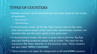
- 3. TYPES OF COUNTERS ŌĆó Broadly counters can be classified into two types based on the modes of operation. ŌĆó Synchronous ŌĆó Asynchronous ŌĆó In Synchronous mode, all the flip-flops receive input at the same time and produce output at the same time. Synchronous counters are counters that use the clock signal at the same time. ŌĆó In Asynchronous mode, the clock is given only to the first flip flop and each flipflop produces output one at a time. The input for the successive flip-flops depends on the previous ones. These counters are also called ŌĆ£RIPPLE COUNTERSŌĆØ. ŌĆó These counters can again be categorized as UP and DOWN counters.
- 4. WHY SYNCHRONOUS COUNTERS? ŌĆó The major drawback in asynchronous counters is that they are limited to high frequencies due to the propagation delay. ŌĆó Synchronous counters can be operated at higher frequencies. ŌĆó Synchronous counters are faster in operation. ŌĆó Easy to design. ŌĆó No delay in synchronous counters.
- 5. TABLE OF CONTENTS ŌĆó MOD 4 Asynchronous ŌĆó MOD 4 Synchronous ŌĆó MOD 7 Asynchronous ŌĆó Specialized IC for Counters ŌĆó MOD 8 Asynchronous ŌĆó MOD 8 Synchronous ŌĆó MOD 16 Asynchronous ŌĆó MOD 16 Synchronous ŌĆó Applications of Counter
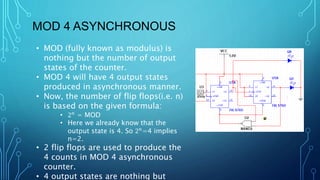
- 6. MOD 4 ASYNCHRONOUS ŌĆó MOD (fully known as modulus) is nothing but the number of output states of the counter. ŌĆó MOD 4 will have 4 output states produced in asynchronous manner. ŌĆó Now, the number of flip flops(i.e. n) is based on the given formula: ŌĆó 2Øæø = MOD ŌĆó Here we already know that the output state is 4. So 2Øæø =4 implies n=2. ŌĆó 2 flip flops are used to produce the 4 counts in MOD 4 asynchronous counter. ŌĆó 4 output states are nothing but
- 7. O/P-1(01) O/P- 2(10) These are some of the outputs of MOD 4 asynchronous counters. Q0 is LSB(Least Significant Bit) and Q1 is MSB (Most Significant Bit). ’üČ The first figure represents output 1 with Q1=0 & Q0=1 i.e. 01(Binary for 1) ’üČ The second figure represents output 2 with Q1=1 & Q0=0 i.e. 10(Binary for 2) O/P-output
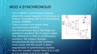
- 8. MOD 4 SYNCHRONOUS ŌĆó This is MOD 4 synchronous counter where the count happens in two ways as follows: ascending (UP) or in descending manner (DOWN). ŌĆó These counters are easier than asynchronous counters. ŌĆó Like the previous one,2 flip flops are needed to produce the 4 output states. The difference is that in synchronous counters, the output changes simultaneously due to the common clock pulse and the count is done sequentially in synchronous counter. ŌĆó Here the counter counts from 0 to 3 (00
- 9. O/P-2(10) O/P-3(11) Here are some of the outputs of the MOD 4 synchronous counter with the same Q0 as LSB and Q1 as MSB ’üČ The first figure represents output 2(10 in binary) ’üČ The second figure represents output 3(11 in binary)
- 10. MOD 7 ASYNCHRONOUS ŌĆó From the title, we came to know that the output state is 7. ŌĆó We know to calculate the number of flip flops from the formula =output state (7) ŌĆó Here 7 is not a multiple of 2, hence we may get confused about how to choose the number of flip flops when the output state is not equal to 2Øæø ŌĆó In that case we choose a number which is a multiple of 2, greater and nearer to 7. the number that satisfies all the above conditions is 8(23 ). Hence, we conclude that we should choose the least possible number of flip-flops. ŌĆó It is not fully sequenced. These types of counters are called truncated counters. ŌĆó All the outputs of the flipflop are 2Øæø
- 11. ŌĆó Here we consider MOD 7 as an example. ŌĆó After count 6, it automatically tries to go to count 7 (111 in binary) which is not required here. ŌĆó In that case the value 1 of all the flip-flops moves to the NAND gate. ŌĆó So the output is 0 which is again sent to the clear pins of the respective flip flops that use a NAND gate to reset to the required count between 0 to 5. ŌĆó A Clear pin is a special pin present in T flip-flop (special of JK flip-flop). Once it is activated it resets the flip flop(0) irrespective of a past condition. The clear pin is activated by a logic low (0) signal. In this case, all the flip flop gets reset and the value goes to 0. Hence MOD 7 is achieved. ŌĆó This gave the way for the IC 74293 that is embedded with 4 flip flops and a NAND gate. ŌĆó NAND gate is mainly used to detect the output 1 which is generated by the flip- flops. WORKING OF THE TRUNCATED COUNTERS
- 12. O/P-4 O/P-5 ’üČ The output 4(100 in binary) and output 5(101 in binary) of MOD 7 asynchronous counter is represented here.
- 13. MOD 8 ASYNCHRONOUS ŌĆó MOD 8 Asynchronous counter can be designed using 3 flip-flops. ŌĆó It is a fully sequenced counter. ŌĆó 2Øæø =8 implies n=3 ŌĆó It counts from 000 to 111 i.e. 0 to 7
- 14. O/P-2 O/P-6 LSB is Q0 and MSB is Q2 ’üČ The first figure represents output 2(010 in binary) ’üČ The second figure represents output 6(110 in binary)
- 15. MOD 8 SYNCHRONOUS ŌĆó MOD 8 synchronous counter is designed using 3 flip flops. ŌĆó It is also a fully sequenced counter which counts in a sequential manner from 0 to 7 or 7 to 0. ŌĆó The second flipflop gets its input from the output of first flipflop (Q1), the third flipflop gets its input from the outputs of the first and second flipflop through a AND gate.
- 16. O/P-5 O/P-7 ’üČ The output 5(101 in binary) and output 7(111 in binary) of MOD 8 synchronous counter is given here.
- 17. MOD 16 ASYNCHRONOUS ŌĆó MOD 16 asynchronous counter is designed using 4 flip-flops as per the formula. ŌĆó It counts from 0000 to 1111 i.e. 0 to F(in hexadecimal) ŌĆó The outputs of all the four flip-flops are connected to a four-pin NAND gate ŌĆó Its output is sent to the clear pins of all the flip-flops. ŌĆó The counter has to reset back to 0(0000) after counting 15(1111). ŌĆó In the case of 15, the NAND gate receives 1 in all inputs, it produces an output of 0. ŌĆó This logic 0 activates the clear pin of all flipflops resetting them to count 0.
- 18. O/P-13 O/P-14 Here Q1 is LSB and Q4 is MSB ’üČ The first picture represents output 13 (decimal value) i.e.1101 in binary. It is converted into hexadecimal value as ŌĆśdŌĆÖ and displayed. ’üČ Similarly the next output 14 i.e. 1110 in binary is displayed as ŌĆśEŌĆÖ (Hexadecimal value).
- 19. MOD 16 SYNCHRONOUS ŌĆó MOD 16 synchronous counter can be constructed using 4 flipflops. ŌĆó It can do either up count operation (0-15) or down count operation (15- 0). ŌĆó The second flipflop gets its input from the output of first flipflop (Q1), the third flipflop gets its input from the outputs of the first and second flipflop through a AND gate. ŌĆó The fourth flipflop receives its input from the output of first, second and third flipflops. ŌĆó A trick is to use the output of the previous flipflop along with the output of the previously connected AND gate.
- 20. O/P 12 O/P 14 Here again, Q0 is LSB and Q3 is MSB ’üČ The first figure represents output 12 i.e.1100 in binary (ŌĆ£CŌĆØ in hexadecimal) ’üČ The second one represents output 14 i.e.1110 in binary (ŌĆ£EŌĆØ in hexadecimal)
- 21. UP-DOWN COUNTERS ŌĆó As the name suggests it counts in both ways i.e. from low to high and also from high to low. ŌĆó So these are also called bidirectional counters. ŌĆó They are built using JK flip-flops. ŌĆó Here it is a 4 bit UP-DOWN counter. ŌĆó It counts from 0 to F on one side and F to 0 on the other side. ŌĆó These are self reversing and used in clock divider circuits.
- 22. COUNTS FOR UP-DOWN COUNTER ’üČ Some of the output counts of the UP-DOWN counter
- 23. APPLICATIONS OF COUNTERS ŌĆó Frequency counters ŌĆó Digital clocks ŌĆó Analog to digital converter ŌĆó Calculators etc.,
- 24. 1) C.MURALIDHARAN Assistant Professor, Biomedical Engineering, Rajalakshmi Engineering College 2) A.SUBHA SHREE Student, Biomedical Engineering, Rajalakshmi Engineering College 3) V.A.SAIRAM Student, Biomedical Engineering, Rajalakshmi Engineering College
- 25. REFERENCES: ŌĆó https://www.electronics-tutorials.ws/counter/count_3.html ŌĆó https://www.electronicshub.org/synchronous-counter/ ŌĆó https://www.electronicshub.org/asynchronous-counter/
- 26. THANK YOU