


![ŌĆó Power loss=I2R,elementary length dx
ŌĆó At point C
X=l
ØææØæā = [Øæ¢ ØæÖ ŌłÆ Øæź ]2
Øæ¤ ØææØæź
Øæā =
0
ØæÖ
Øæ¢2 ØæÖ2 ŌłÆ 2ØæÖØæź + Øæź2 Øæ¤ ØææØæź = Øæ¤ Øæ¢2(ØæÖ2Øæź ŌłÆ
2ØæÖØæź2
2
+
Øæź3
3
)
Øæā =
Øæ¢2Øæ¤ØæÖ3
3](https://image.slidesharecdn.com/distributionsystems-150204040603-conversion-gate01-230315100719-860ea07f/85/Distribution-System-29-320.jpg)

![ŌĆó Upto point C is,
ØæēØÉ┤ØÉČ =
0
Øæź
Øæ¢
ØæÖ
2
ŌłÆ Øæź Øæ¤ ØææØæź = Øæ¢Øæ¤
ØæÖØæź
2
ŌłÆ
Øæź2
2
=
Øæ¢Øæ¤
2
[ØæÖØæź ŌłÆ Øæź2]
Maximum voltage drop at midpoint x=l/2
ØæÜØæÄØæźØæ¢ØæÜØæóØæÜ ØææØæ¤Øæ£ØæØ = ir
ØæÖ2
4
ŌłÆ
ØæÖ2
8
=
Øæ¢Øæ¤ØæÖ2
8
=
1
8
Øæ¢ØæÖ Øæ¤ØæÖ =
ØÉ╝Øæģ
8
┬╝ drop of fed at one end
Power loss ,point c
ØææØæā = [Øæ¢
ØæÖ
2
ŌłÆ Øæź ]2
Øæ¤ ØææØæź
Øæā = Øæ¢2
Øæ¤
0
ØæÖ
ØæÖ2
4
ŌłÆ ØæÖØæź + Øæź2
ØææØæź
Øæā =
Øæ¢2
Øæ¤ØæÖ3
12](https://image.slidesharecdn.com/distributionsystems-150204040603-conversion-gate01-230315100719-860ea07f/85/Distribution-System-31-320.jpg)


![ŌĆó Voltage drop in section RQ, ØæēØæģØæä = ØÉ╝ØæģØæä ØæŹØæģØæä
ØæēØæģØæä=[ØÉ╝2(cos Ōłģ2 ŌłÆ ØæŚ sin Ōłģ2)].[ Øæģ2 + ØæŚØæŗ2]
Voltage drop in section PR , ØæēØæāØæģ = ØÉ╝ØæāØæģ ØæŹØæāØæģ
=[ØÉ╝1(cos Ōłģ1 ŌłÆ ØæŚ sin Ōłģ1) + ØÉ╝2(cos Ōłģ2 ŌłÆ ØæŚ sin Ōłģ2)][Øæģ1 + ØæŚØæŗ1].
Sending end voltage ØæēØæā = ØæēØæä + ØæēØæģØæä + ØæēØæāØæä
Sending end current ØÉ╝Øæā = ØÉ╝1 + ØÉ╝2](https://image.slidesharecdn.com/distributionsystems-150204040603-conversion-gate01-230315100719-860ea07f/85/Distribution-System-37-320.jpg)

![ŌĆó 2. power factor referred to respective load voltages
Voltage drop in section RQ is given, ØæēØæģØæä = ØÉ╝2 ØæŹØæģØæä
ØæēØæģØæä=[ØÉ╝2(cos Ōłģ2 ŌłÆ ØæŚ sin Ōłģ2)].[ Øæģ2 + ØæŚØæŗ2]
ØæēØæģ = ØæēØæä +drop of voltage in section RQ=ØæēØæģ ØæÄØæøØæöØæÖØæÆ Øæ£Øæō ╬▒.
ØÉ╝1 = ØÉ╝1(cos Ōłģ1 ŌłÆ ØæŚ sin Ōłģ1) w.r.t voltage ØæēØæģ
ØÉ╝1 = ØÉ╝1(cos(Ōłģ1ŌłÆ╬▒) ŌłÆ ØæŚ sin(Ōłģ1 ŌłÆ ╬▒)) w.r.t voltage ØæēØæä
ØÉ╝ØæāØæģ = ØÉ╝1 + ØÉ╝2
=ØÉ╝1(cos(Ōłģ1ŌłÆ╬▒) ŌłÆ ØæŚ sin(Ōłģ1 ŌłÆ ╬▒)) +ØÉ╝2(cos Ōłģ2 ŌłÆ ØæŚ sin Ōłģ2)
ØæēØæģØæä=[ØÉ╝1(cos(Ōłģ1ŌłÆ╬▒) ŌłÆ ØæŚ sin(Ōłģ1 ŌłÆ ╬▒)) +ØÉ╝2(cos Ōłģ2 ŌłÆ ØæŚ sin Ōłģ2)].[Øæģ1 + ØæŚØæŗ1]
Sending end voltage ØæēØæā, ØæēØæā = ØæēØæä + ØæēØæģØæä + ØæēØæāØæģ](https://image.slidesharecdn.com/distributionsystems-150204040603-conversion-gate01-230315100719-860ea07f/85/Distribution-System-39-320.jpg)


More Related Content
Similar to Distribution System (20)
More from Saravanan A (14)


Recently uploaded (20)


Distribution System
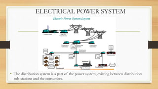
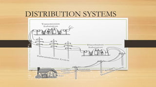
- 2. ELECTRICAL POWER SYSTEM ŌĆó The distribution system is a part of the power system, existing between distribution sub-stations and the consumers.
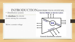
- 4. INTRODUCTION(DISTRIBUTION SYSTEMS) ŌĆó Distribution systems To distribute the electric power among the consumer. Below a certain voltage General distribution scheme
- 5. Requirements of good distribution systems ŌĆó Continuity in the power supply must be ensured. ŌĆó Voltage must not vary more than the prescribed limits.(Ōłō5%). ŌĆó Efficiency of line must be high as possible. ŌĆó Safe from consumer point of view. ŌĆó Layout should not effect the appearance of locality. ŌĆó Line should not be overloaded.
- 6. Distribution system is further classified on the basis of voltage 1.primary distribution systems 2.secondary distribution systems ŌĆó Primary Distribution:-The part of the electrical-supply system existing between the distribution substations and the distribution transformers is called the primary system. ŌĆó Secondary Distribution:-The secondary distribution system receives power from the secondary side of distribution transformers at low voltage and supplies power to various connected loads via service lines.
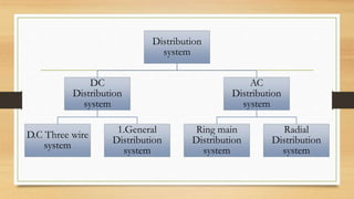
- 7. Distribution system DC Distribution system D.C Three wire system 1.General Distribution system AC Distribution system Ring main Distribution system Radial Distribution system
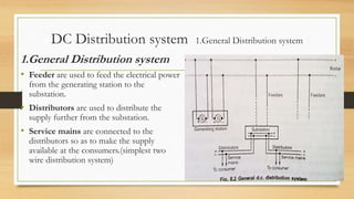
- 8. DC Distribution system 1.General Distribution system 2. D.C Three wire system 1.General Distribution system ŌĆó Feeder are used to feed the electrical power from the generating station to the substation. ŌĆó Distributors are used to distribute the supply further from the substation. ŌĆó Service mains are connected to the distributors so as to make the supply available at the consumers.(simplest two wire distribution system)
- 9. 2.D.C Three wire system ŌĆó Voltage level can not be increased readily like a.c. ŌĆó Method:-two generators are connected in series -each is generating a voltage of V volts -common point is neutral from where neutral wire is run. (too expensive , use to double the transmission voltage) ŌĆó Demand :-consumers demanding higher voltage are connected to the two lines. -consumers demanding less voltage are connected between any one line and neutral.
- 10. D.C Three wire system
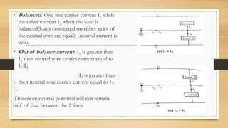
- 11. ŌĆó Balanced:-One line carries current I1 while the other current I2.when the load is balanced(loads connected on either sides of the neutral wire are equal) .neutral current is zero. ŌĆó Out of balance current:-I1 is greater than I2 then neutral wire carries current equal to I1-I2 -I2 is greater than I1 then neutral wire carries current equal to I2- I1. (Direction).neutral potential will not remain half of that between the 2 lines.
- 12. Single generator having twice the line ŌĆó Two small d.c machines are connected across the line in series which are mechanically coupled to a common shaft . These are called balancers. ŌĆó load is balanced:-machines work as the d.c motors. ŌĆó Out of balance:-machine connected to lightly loaded side acts as motor , heavily loaded side acts as generator. Energy is transferred from lightly loaded side to heavily loaded side as machine as motor drives the machine as generator.
- 13. AC Distribution system 1.Radial Distribution system 2.Ring main Distribution system 1.Radial Distribution system ŌĆó only one/single path is connected between each Distributor and substation is called radial Distribution system. ŌĆó Fault occurs either on feeder or a distributor, all the consumers connected to that distributor will get affected. ŌĆó In India, 99% of distribution of power is by radial distribution system only.
- 14. Advantages: ŌĆó Its initial cost is minimum. ŌĆó Simple in planning, design and operation. ŌĆó Useful when the generation is at low voltage.. ŌĆó Station is located at the center of the load Disadvantages: ŌĆó Distributor nearer to the feeding end is heavily loaded. ŌĆó The consumers at the far end of the feeder would be subjected to series voltage fluctuations with the variations in load.
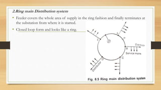
- 15. 2.Ring main Distribution system ŌĆó Feeder covers the whole area of supply in the ring fashion and finally terminates at the substation from where it is started. ŌĆó Closed loop form and looks like a ring.
- 16. Advantages: ŌĆó Less conductor material is required as each part of the ring carries less current than in the radial system. ŌĆó Less voltage fluctuations. Disadvantage: ŌĆó It is difficult to design when compared to the designing of a radial system.
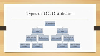
- 17. Types of D.C Distributors D.C Distributors Concentrated loads Fed at both the end Ends at Unequal voltages End at Equal voltages Fed at one end Distributed loads Fed at one end Fed at both the end End at Equal voltages Ends at Unequal voltages
- 18. ŌĆó Concentrated loads:-load which are acting at particular points of the distributor are called concentrated loads. ŌĆó Distributed loads:-load which spread over the particular distance of the distributor are called distributed load.(no load condition practical) D.C Distributor with Concentrated loads ŌĆó Classified 1. Fed at one end 2.Fed at both the ends
- 19. 1.Fed at one end(Concentrated loads)
- 20. ŌĆó Fed at one end A-AŌĆÖ. ŌĆó Applying KCL at various points we get, i1=I1+I2+I3,i2=I2+I3 and i3=I3 ŌĆó the wire AŌĆÖBŌĆÖ is the return wire of the distributor rŌĆÖ=resistance per unit length of conductor in ╬® ŌĆó Voltage drop tabulated as, section Drop section Drop Aa i1l1rŌĆÖ AŌĆÖaŌĆÖ i1l1rŌĆÖ ab i2(l2-l1)rŌĆÖ aŌĆÖbŌĆÖ i2(l2-l1)rŌĆÖ bc i3(l3-l2)rŌĆÖ bŌĆÖcŌĆÖ i3(l3-l2)rŌĆÖ
- 21. ŌĆó In practice , the resistance of go and return conductor per unit length is assumed to be r=2rŌĆÖ. ŌĆó r1=2r1ŌĆÖ, r2=2r2ŌĆÖ, r3=2r3ŌĆÖ ŌĆó The total drop in the distributor is =r1i1l1+r2i2(l2-l1)+r3i3(l3-l2)
- 22. Current loading and voltage drop diagram
- 23. 2.Fed at both the ends(Concentrated loads) 1.End at Equal voltages ŌĆó A and B maintained at equal voltage ŌĆó ŌĆśbŌĆÖ be the point of minimum potential(the load point where the current are coming from both the side of distributor is the point of minimum potential. Let x be supplied by point A while y be supplied by point B, y=I2-x
- 24. ŌĆó As both the point A and B are maintained at same voltage, drop in section Aa must be equal to drop in section Bb. i1r1+i2r2=i3r3+i4r4 (I1+x)r1+xr2=(I2-x)r3+(I2+I3-x)r4 ŌĆó All current known , x and voltage drop can be calculated Current loading and voltage drop diagram
- 25. 2.Ends at Unequal voltages ŌĆó A and B maintained at different voltage ŌĆó ŌĆśbŌĆÖ be the point of minimum potential. ŌĆó Let x be supplied by point A while y be supplied by point B, y=I2-x ŌĆó Voltage drop between A and B = Voltage drop over AB ŌĆó If voltage of A is V1 and is greater than voltage of B which is V2 then, V1-V2=drop in all the section of AB ŌĆó The same equation can be written as, V1-drops over Ab= V2-drops over Bb
- 26. V1-i1r1-i2r2=V2-i3r3-i4r4 V1-(I1+x)r1-xr2=V2-(I2-x)r3-(I2+I3-x)r4 Here V1 and V2 are known ,obtain x Current loading and voltage drop diagram
- 27. D.C Distributor with Uniformly Distributed load ŌĆó Classified 1. Fed at one end 2.Fed at both the ends 1.Fed at one end (Distributed load ) ŌĆó Uniformly distributed load on 2 wire distributor , fed at one end I amperes per meter Total voltage drop is to be obtained by considering a point C(distance x),feeding end A ŌĆó Current tapped at point C is =total current ŌĆō current up to point ŌĆśCŌĆÖ=i├Ś ØæÖ ŌłÆ Øæ¢ ├Ś Øæź=i(l├Ś Øæź)
- 28. ŌĆó dx near point C , its resistance rdx dV=i(l-x)rdx Total voltage drop upto point C Upto B, x=l ØæēØÉ┤ØÉČ = 0 Øæź Øæ¢ ØæÖ ŌłÆ Øæź Øæ¤ ØææØæź = Øæ¢Øæ¤ 0 Øæź ØæÖ ŌłÆ Øæź ØææØæź = Øæ¢Øæ¤(ØæÖØæź ŌłÆ Øæź2 2 )0 Øæź ØæēØÉ┤ØÉČ=Øæ¢Øæ¤(ØæÖØæź ŌłÆ Øæź2 2 ) volts equation of parabola ØæēØÉ┤ØÉĄ=Øæ¢Øæ¤(ØæÖ ├Ś ØæÖ ŌłÆ ØæÖ├ŚØæÖ 2 )=ir ØæÖ2 2 = 1 2 (il)(rl) ØæēØÉ┤ØÉĄ = 1 2 ØÉ╝Øæģ
- 29. ŌĆó Power loss=I2R,elementary length dx ŌĆó At point C X=l ØææØæā = [Øæ¢ ØæÖ ŌłÆ Øæź ]2 Øæ¤ ØææØæź Øæā = 0 ØæÖ Øæ¢2 ØæÖ2 ŌłÆ 2ØæÖØæź + Øæź2 Øæ¤ ØææØæź = Øæ¤ Øæ¢2(ØæÖ2Øæź ŌłÆ 2ØæÖØæź2 2 + Øæź3 3 ) Øæā = Øæ¢2Øæ¤ØæÖ3 3
- 30. 2.Fed at both the ends (Uniformly Distributed load) 1.End at Equal voltages fed at point A and B are maintained at equal voltage The total current to be supplied is il amperes. As two end voltage are equal ,each end will supply half the required current i.e Øæ¢ØæÖ 2 . Midpoint distance l/2,point C at a distance x , current feeding is il/2 (A) Current at C= Øæ¢ØæÖ 2 ŌłÆ Øæ¢Øæź = Øæ¢ ØæÖ 2 ŌłÆ Øæź Voltage drop over length dx is, ØææØæŻ = Øæ¢ ØæÖ 2 ŌłÆ Øæź Øæ¤ ØææØæź
- 31. ŌĆó Upto point C is, ØæēØÉ┤ØÉČ = 0 Øæź Øæ¢ ØæÖ 2 ŌłÆ Øæź Øæ¤ ØææØæź = Øæ¢Øæ¤ ØæÖØæź 2 ŌłÆ Øæź2 2 = Øæ¢Øæ¤ 2 [ØæÖØæź ŌłÆ Øæź2] Maximum voltage drop at midpoint x=l/2 ØæÜØæÄØæźØæ¢ØæÜØæóØæÜ ØææØæ¤Øæ£ØæØ = ir ØæÖ2 4 ŌłÆ ØæÖ2 8 = Øæ¢Øæ¤ØæÖ2 8 = 1 8 Øæ¢ØæÖ Øæ¤ØæÖ = ØÉ╝Øæģ 8 ┬╝ drop of fed at one end Power loss ,point c ØææØæā = [Øæ¢ ØæÖ 2 ŌłÆ Øæź ]2 Øæ¤ ØææØæź Øæā = Øæ¢2 Øæ¤ 0 ØæÖ ØæÖ2 4 ŌłÆ ØæÖØæź + Øæź2 ØææØæź Øæā = Øæ¢2 Øæ¤ØæÖ3 12
- 32. ŌĆó 2.Ends at Unequal voltages ŌĆó Let point C be the point of minimum potential which at a distance x from feeding point A ŌĆó The current supplied by the feeding point A is ix ŌĆó The current supplied by the feeding point B is i(l-x) ŌĆó V1-drops over AC= V2-drops over BC ŌĆó In case of distributed load the drop is given by Øæ¢Øæ¤ØæÖ2 2 for a length of l ØæēØÉ┤ØÉČ = Øæ¢Øæ¤Øæź2 2 ØæŻØæ£ØæÖØæĪØæĀ ØæēØÉĄØÉČ = Øæ¢Øæ¤(ØæÖ ŌłÆ Øæź)2 2 ØæŻØæ£ØæÖØæĪØæĀ Øæē1 ŌłÆ Øæ¢Øæ¤Øæź2 2 = Øæē2 ŌłÆ Øæ¢Øæ¤(ØæÖ ŌłÆ Øæź)2 2 X?
- 33. Ring main distributor with interconnection ŌĆó Cable is arranged in the Loop fashion,fed at only one point ŌĆó Use for large area hence voltage drop across the various section become larger(excessive voltage drop). ŌĆó Solution:-distant point of ring distributor are joined together by a conductor this is called interconnection. ŌĆó TheveninŌĆÖs theorem ØÉ╝ = ØÉĖØæ£ ØæģØæćØÉ╗ + ØæģØÉĘØÉ║
- 34. AC Distribution ŌĆó Advantages of AC ŌĆó Cheaper transformation between voltages ŌĆó Easy to switch off ŌĆó Less equipment needed ŌĆó More economical in general ŌĆó Rotating field
- 35. Methods of solving A.C Distribution problem ŌĆó 1.power factor referred to receiving end voltage ŌĆó Resistance R , reactance X ŌĆó Impedance of section PR is given by, ØæŹØæāØæģ = Øæģ1 + ØæŚØæŗ1. ŌĆó Impedance of section RQ is given by, ØæŹØæģØæä = Øæģ2 + ØæŚØæŗ2. ŌĆó The load current at point R is ØÉ╝1, ØÉ╝1 = ØÉ╝1(cos Ōłģ1 ŌłÆ ØæŚ sin Ōłģ1) ŌĆó The load current at point Q is ØÉ╝2, ØÉ╝2 = ØÉ╝2(cos Ōłģ2 ŌłÆ ØæŚ sin Ōłģ2) ŌĆó Current in section RQ is nothing but ØÉ╝ØæģØæä = ØÉ╝2 = ØÉ╝2(cos Ōłģ2 ŌłÆ ØæŚ sin Ōłģ2) ŌĆó Current in section PR is ØÉ╝ØæāØæģ = ØÉ╝1 + ØÉ╝2=ØÉ╝1(cos Ōłģ1 ŌłÆ ØæŚ sin Ōłģ1)+ØÉ╝2(cos Ōłģ2 ŌłÆ ØæŚ sin Ōłģ2)
- 36. 1.power factor referred to receiving end voltage
- 37. ŌĆó Voltage drop in section RQ, ØæēØæģØæä = ØÉ╝ØæģØæä ØæŹØæģØæä ØæēØæģØæä=[ØÉ╝2(cos Ōłģ2 ŌłÆ ØæŚ sin Ōłģ2)].[ Øæģ2 + ØæŚØæŗ2] Voltage drop in section PR , ØæēØæāØæģ = ØÉ╝ØæāØæģ ØæŹØæāØæģ =[ØÉ╝1(cos Ōłģ1 ŌłÆ ØæŚ sin Ōłģ1) + ØÉ╝2(cos Ōłģ2 ŌłÆ ØæŚ sin Ōłģ2)][Øæģ1 + ØæŚØæŗ1]. Sending end voltage ØæēØæā = ØæēØæä + ØæēØæģØæä + ØæēØæāØæä Sending end current ØÉ╝Øæā = ØÉ╝1 + ØÉ╝2
- 38. 2. power factor referred to respective load voltages
- 39. ŌĆó 2. power factor referred to respective load voltages Voltage drop in section RQ is given, ØæēØæģØæä = ØÉ╝2 ØæŹØæģØæä ØæēØæģØæä=[ØÉ╝2(cos Ōłģ2 ŌłÆ ØæŚ sin Ōłģ2)].[ Øæģ2 + ØæŚØæŗ2] ØæēØæģ = ØæēØæä +drop of voltage in section RQ=ØæēØæģ ØæÄØæøØæöØæÖØæÆ Øæ£Øæō ╬▒. ØÉ╝1 = ØÉ╝1(cos Ōłģ1 ŌłÆ ØæŚ sin Ōłģ1) w.r.t voltage ØæēØæģ ØÉ╝1 = ØÉ╝1(cos(Ōłģ1ŌłÆ╬▒) ŌłÆ ØæŚ sin(Ōłģ1 ŌłÆ ╬▒)) w.r.t voltage ØæēØæä ØÉ╝ØæāØæģ = ØÉ╝1 + ØÉ╝2 =ØÉ╝1(cos(Ōłģ1ŌłÆ╬▒) ŌłÆ ØæŚ sin(Ōłģ1 ŌłÆ ╬▒)) +ØÉ╝2(cos Ōłģ2 ŌłÆ ØæŚ sin Ōłģ2) ØæēØæģØæä=[ØÉ╝1(cos(Ōłģ1ŌłÆ╬▒) ŌłÆ ØæŚ sin(Ōłģ1 ŌłÆ ╬▒)) +ØÉ╝2(cos Ōłģ2 ŌłÆ ØæŚ sin Ōłģ2)].[Øæģ1 + ØæŚØæŗ1] Sending end voltage ØæēØæā, ØæēØæā = ØæēØæä + ØæēØæģØæä + ØæēØæāØæģ
- 40. THANK YOU