


![COUNTERS [Synchronous and Asynchronous]](https://cdn.slidesharecdn.com/ss_thumbnails/counters-211217083059-thumbnail.jpg?width=560&fit=bounds)


More Related Content
Similar to presentationforcountersin digitalelectronics (20)
Recently uploaded (20)


presentationforcountersin digitalelectronics
- 1. Counters Presented By: Neetika Yadav
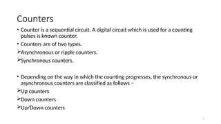
- 2. 2 Counters ŌĆó Counter is a sequential circuit. A digital circuit which is used for a counting pulses is known counter. ŌĆó Counters are of two types. ’āśAsynchronous or ripple counters. ’āśSynchronous counters. ŌĆó Depending on the way in which the counting progresses, the synchronous or asynchronous counters are classified as follows ŌłÆ ’āśUp counters ’āśDown counters ’āśUp/Down counters
- 3. 3 Types ’ü▒Asynchronous Counters (or Ripple counters) ŌĆó the clock signal (CLK) is only used to clock the first FF. ŌĆó Each FF (except the first FF) is clocked by the preceding FF. ’ü▒Synchronous Counters ŌĆó the clock signal (CLK) is applied to all FF ŌĆó all FF shares the same clock signal, ŌĆó the output will change at the same time.
- 4. 4 Modulus (MOD) ŌĆó the number of states it counts in a complete cycle before it goes back to the initial state. No. of states = 2n = MOD number Where n is no of flip flops E.g. MOD-4 use 2 FF (2-bit), MOD-8 use 3 FF (3-bit), etc..) ŌĆó Modulus (MOD) ŌĆō the number of states it counts in a complete cycle before it goes back to the initial state. So in general, an n-bit ripple counter is called as modulo-N counter.
- 5. 5 Ripple Counter ŌĆó an asynchronous counter where only the first flip-flop is clocked by an external clock. ŌĆó All subsequent flip-flops are clocked by the output of the preceding flip-flop. ŌĆó Asynchronous counters are also called ripple-counters because of the way the clock pulse ripples it way through the flip-flops.
- 6. 6 2-bit ripple up counter External clock is applied to the clock input of flip-flop A and QA output is applied to the clock input of the next flip-flop i.e. FF-B. It contains two flip flops. A 2-bit ripple counter can count up to 4 states. It counts from 0 to 3.
- 7. 7 2 bit Ripple Down Counter It contains two flip flops. A 2-bit ripple counter can count up to 4 states. It is known as down counter as it counts down from 3 to 0.
- 8. 8 Up/Down Counter ŌĆó In the UP/DOWN ripple counter all the FFs operate in the toggle mode. ŌĆó So either T flip-flops or JK flip-flops are to be used. ŌĆó The LSB flip-flop receives clock directly. But the clock to every other FF is obtained from (Q or Q bar) output of the previous FF. ŌĆó UP counting mode (M=0): The Q output of the preceding FF is connected to the clock of the next stage if up counting is to be achieved. For this mode, the mode select input M is at logic 0 (M=0). ŌĆó DOWN counting mode (M=1) : If M =1, then the Q bar output of the preceding FF is connected to the next FF. This will operate the counter in the down counting mode.
- 9. 9 3-bit binary up/down ripple counter ŌĆó 3-bit : hence three FFs are required. ŌĆó UP/DOWN : So a mode control input is essential. ŌĆó For a ripple up counter, the Q output of preceding FF is connected to the clock input of the next one. ŌĆó For a ripple down counter, the Q bar output of preceding FF is connected to the clock input of the next one.
- 10. 10 3-bit binary up/down ripple counter
- 11. 11 Working ŌĆó Case 1: With M = 0 (Up counting mode) ŌĆó If M = 0 and M bar = 1, then the AND gates 1 and 3 in fig. will be enabled whereas the AND gates 2 and 4 will be disabled. ŌĆó Hence QA gets connected to the clock input of FF-B and QB gets connected to the clock input of FF- C. ŌĆó These connections are same as those for the normal up counter. Thus with M = 0 the circuit work as an up counter. ŌĆó Case 2: With M = 1 (Down counting mode) ŌĆó If M = 1, then AND gates 2 and 4 in fig. are enabled whereas the AND gates 1 and 3 are disabled. ŌĆó Hence QA bar gets connected to the clock input of FF-B and QB bar gets connected to the clock input of FF-C. ŌĆó These connections will produce a down counter. Thus with M = 1 the circuit works as a down counter.
- 12. 12 Synchronous counters ŌĆó If the "clock" pulses are applied to all the flip-flops in a counter simultaneously ŌĆó changes in the output occur in ŌĆ£synchronisationŌĆØ with the clock signal.
- 13. 13 Ring Counter ŌĆó By looping the output back to the input, (feedback) we can convert a standard shift register circuit into a ring counter. Consider the circuit below.
Editor's Notes
- #9: Let the selection of Q and Q bar output of the preceding FF be controlled by the mode control input M such that, If M = 0, UP counting. So connect Q to CLK. If M = 1, DOWN counting. So connect Q bar to CLK.