Vapor power cycles are thermodynamic processes that convert heat into mechanical work using a vapor-phase working fluid. They involve processes like compression, heating, expansion, and cooling to extract maximum heat from a source and convert it into useful work. Efficiency depends on temperature, pressure, working fluid, and design. The document discusses the Carnot and Rankine cycles as examples of vapor power cycles. It covers the processes, diagrams, components, efficiencies, applications, and environmental impacts of vapor power cycles.
A turbine is a machine that converts kinetic energy or pressure from fluids like water, steam, gas or air into rotational motion. There are different types of turbines including impulse turbines like Pelton and cross-flow turbines which use kinetic energy, and reaction turbines like Francis and Kaplan which use pressure changes. Advanced cycles have been developed for gas turbines like wet compression, steam injection and combined cycles to improve efficiency. Nano-turbines have also been designed but have much lower efficiencies than macro-scale turbines due to effects like water slippage and flow disruption at the nanoscale.
This document provides an overview of impulse steam turbines, including:
1) It describes the basic working principle of impulse turbines which use nozzles to convert steam's pressure energy to kinetic energy that rotates the turbine's blades and shaft.
2) It discusses key components like nozzles, rotor blades, and applications in power generation, marine propulsion, and cogeneration systems.
3) Important design considerations for impulse turbines are outlined, such as optimizing blade geometry, steam flow path, material selection, and rotor dynamics to maximize efficiency and performance.
Basic Mechanical Engineering- Hydraulic turbinesSteve M S
Ìý
The document discusses different types of hydraulic turbines used to convert hydraulic energy from falling or flowing water into mechanical energy. It classifies turbines based on the type of energy at the inlet as either impulse turbines (only kinetic energy) or reaction turbines (both pressure and kinetic energy). It describes the Pelton wheel and Francis turbine as examples of each type. It further classifies turbines based on the main flow direction and provides ranges for suitable head based on specific speed. In summary, the document provides an overview of common hydraulic turbine classifications and examples like the Pelton and Francis turbines used for high and medium heads respectively.
This document discusses DC motor drives using DC-DC converters. It begins with an abstract that outlines studying the design of DC drives using DC-DC choppers and how duty cycle affects motor speed and armature voltage. It then introduces DC-DC converter drives, explaining they can control motor speed by varying duty cycle and provide regenerative braking. The body discusses the operating modes of DC chopper drives including power control, regenerative braking control, and their waveforms. It also covers two-quadrant and four-quadrant drives, explaining the different motor and regeneration quadrants that each can operate in.
STUDY AND ANALYSIS OF STEAM TURBINE AND TURBINE LOSSESMohammed Sameer
Ìý
This document provides an abstract for a mini-project presentation on studying and analyzing steam turbines and turbine losses at a thermal power plant (KTPS). The abstract introduces the objectives of studying steam turbine performance and evaluating turbine losses. It also briefly discusses the basic components and working of a steam turbine power plant. The document further includes sections on turbine theory, classifications, construction, components, losses, data collection and calculations for turbine efficiency.
Design of Hydraulic and Pneumatic Systems Digital Material.pdfSriramadasusreenu
Ìý
The document provides details about a course outline for a fluid power principles and hydraulic pumps course. The course covers topics like fluid power systems, types of fluids, properties of fluids, basics of hydraulics, Pascal's law, pump classification, construction and working, hydraulic actuators and control components. It includes learning objectives for each lecture and provides information about various types of pumps like gear pumps, vane pumps, piston pumps and their working. It also discusses hydraulic actuators like cylinders and motors and control components like direction control valves, flow control valves and pressure control valves.
Construction and Working of Centrifugal Pump.pptxShubham Chavanke
Ìý
This document provides an overview of the construction and working of centrifugal pumps. It describes the key components of a centrifugal pump as an impeller and casing. The impeller transfers energy from the motor and accelerates the fluid outward, while the casing converts the velocity to a controlled flow out of the pump. It works on the principle of centrifugal force by generating low pressure inside the casing as the impeller rotates, causing fluid at high pressure to flow in and be pushed out. Centrifugal pumps are classified by flow type and widely used in industries like petroleum, pharmaceuticals, and power plants to transport fluids.
This document discusses fluid couplings and hydraulic torque converters. It describes their construction, working principles, efficiencies, uses, and differences. A fluid coupling transmits power between shafts using an liquid medium, with no direct contact. A hydraulic torque converter also uses liquid to transmit variable torque without gears or clutches, and can multiply torque up to 5 times. Both are used in automotive and industrial applications where smooth starting torque is required.
This document discusses water turbines used in hydroelectric power plants. It defines key terms like specific energy, gross head, gross specific hydraulic energy, and gross power. It also describes different types of turbines like impulse turbines (Pelton, Turgo) and reaction turbines (Francis, Kaplan, Bulb) and compares their characteristics. It discusses concepts like specific speed, speed number, unit and specific quantities that are used to classify and select turbines based on factors like head, rotational speed, efficiency and more. It also provides examples of problems calculating speed number, specific speed and selecting the suitable turbine type.
The document provides an overview of the Stirling engine, including its history, working principle, components, configurations, efficiency, applications and advantages/disadvantages. It was invented in 1816 by Robert Stirling as a safer alternative to steam engines. The Stirling engine works on a closed regenerative thermodynamic cycle to convert heat into mechanical work using a fixed quantity of working fluid. Its components include a working gas, displacer/power pistons, heat exchangers and a regenerator. Common configurations are the alpha, beta and gamma types. Applications include power generation, cooling and pumping. Advantages are high efficiency and fuel flexibility, while disadvantages include cost and sealing challenges.
This document describes the impulse turbine known as the Pelton turbine. It consists of a wheel with buckets that is struck by one or more high-velocity jets of water. The jet is produced by a nozzle that converts the potential energy of water from a reservoir into kinetic energy. As the jet strikes the buckets, it transfers momentum which spins the wheel and powers the turbine's shaft. Key components include the runner, buckets, nozzle, and casing. The document provides details on dimensions, speed ratio, jet ratio, and the number of jets used.
The document discusses electrical drives and control. It defines an electrical drive as a unit consisting of an electric motor, energy transmitting shaft, and control equipment. Drive systems combine electrical drives with corresponding loads. Advantages of electrical drives include feasible control characteristics, wide speed and torque ranges, higher efficiency, lower noise, and easier maintenance. Examples of electrical drives include AC and DC drives. Types of electrical drives include group drives, individual drives, and multimotor drives. Group drives have one motor driving multiple machines while individual drives have one dedicated motor per machine. Selection of motors depends on the load characteristics.
This document provides an overview of impulse turbines. It begins with an introduction that defines steam turbines and classifies them into impulse and reaction turbines. It then describes the basic components of an impulse turbine, including the penstock, spear and nozzle, casing, runner with buckets, and breaking jet. The principle and operation section explains that impulse turbines work on the principle of impulse, where the kinetic energy of steam impinging on the blades produces a force that changes the momentum and causes rotation. A pressure-velocity diagram is also included to illustrate how steam expands in the nozzle. The document concludes by noting that reaction turbines are more commonly used for electricity production from steam or hydro due to lower heads and higher flows.
This document summarizes a seminar presentation on fluid couplings. It includes sections on the introduction, history, construction, operation, explanation, advantages, and applications of fluid couplings. A fluid coupling transmits rotating mechanical power between two shafts without a direct mechanical connection using an intermediate fluid like oil. It was invented in the early 20th century by German engineer Hermann Föttinger. A fluid coupling consists of a pump impeller on the driving shaft and a turbine runner on the driven shaft enclosed in a housing filled with fluid.
1) Steam turbines are important prime movers that convert the thermal energy of steam into useful work. They operate using the principle that steam flowing over curved turbine blades imparts a force and causes the blades to rotate.
2) Steam turbines can be classified as impulse or reaction turbines depending on where the pressure drop of steam occurs. Impulse turbines only cause a pressure drop in nozzles, while reaction turbines cause a pressure drop both in nozzles and over rotor blades.
3) Steam condensers are heat transfer devices that condense exhaust steam from turbines using cooling water. The condensed steam, or condensate, is returned to boilers to be reused, saving water costs.
1) An actuator is a device that produces motion or action in response to an input signal. Common types of actuators include hydraulic, pneumatic, mechanical, electrical, and piezoelectric actuators.
2) Actuators work by converting an input energy source like electricity, air pressure, or hydraulic fluid pressure into motion. Common applications include valves, car door openers, hydraulic jacks, and brakes.
3) Hydraulic and pneumatic actuators are often used to transmit power and control motion due to their ability to generate high forces and respond quickly. Common configurations include single-acting and double-acting cylinders and rotary motors.
The centrifugal pump consists of an impeller that rotates within a casing and uses centrifugal force to convert mechanical energy into hydraulic energy or pressure energy. As fluid enters the center of the impeller, the rotating vanes accelerate the fluid and discharge it outward into the casing. The casing, typically a volute, then converts the fluid's kinetic energy into increased pressure, causing the fluid to exit the pump at a higher pressure than when it entered. Proper pump operation relies on balancing factors such as suction head, delivery head, and mechanical efficiency to move fluid while avoiding cavitation that can damage pump components.
Camless engines eliminate mechanical linkages like camshafts and instead use electronic control units and sensors to control intake and exhaust valves. This allows for infinite variability of valve timing, lift, and duration compared to conventional engines with static cam profiles. In a camless engine, solenoid valves controlled by the ECU open and close the valves using pressurized hydraulic fluid. Potential advantages include higher torque throughout the rev range, reduced emissions, and improved fuel economy.
Steam turbines and their classifications by tharun kumar malapati.pptxtharunmalapati4707
Ìý
Steam turbines work by converting the thermal energy of high-pressure steam into mechanical energy. They are classified based on their working principles as either impulse or reaction turbines, and by the direction of steam flow as either axial or radial flow turbines. Steam turbines can be further classified based on pressure, number of stages, and wheel arrangement. They are commonly used for power generation and have advantages of high efficiency and compact size but also have disadvantages of high costs and slower response times compared to other technologies.
Project management involves three key phases: planning, scheduling, and controlling. Planning involves setting objectives, identifying activities, and estimating resources and costs. Scheduling determines the start and finish times of activities using techniques like CPM and PERT to identify the critical path. Controlling monitors progress against the plan and allows for revisions if needed. Effective project management requires thorough planning, scheduling of activities and resources, and ongoing controlling to ensure projects are completed on time and on budget.
The document discusses several methods for producing hydrogen through water splitting, including:
- Steam reforming of methane, the most common current method.
- Electrolysis, where an electric current splits water into hydrogen and oxygen. More efficient variations include steam electrolysis and thermochemical electrolysis.
- Photochemical and photobiological systems use sunlight to drive the water splitting reaction.
- Thermal water splitting uses very high temperatures of around 1000°C.
- Gasification and biomass conversion also produce hydrogen from other feedstocks.
Low current electrolysis is discussed as a more efficient method, similar to the water splitting that occurs in photosynthesis. Producing hydrogen directly from water without electrolysis is also mentioned. Overall
Presentation - Building the Green Hydrogen Economy.pptxMdHelalHossain6
Ìý
This presentation discusses the potential for green hydrogen to support a renewable energy economy. It notes that hydrogen energy is already being used in three surprising applications: fuel cells to power buses and trucks, hydrogen to heat homes in Japan, and blending hydrogen into natural gas pipelines in the US and Europe. The presentation also compares the costs of hydrogen storage versus lithium-ion batteries for shifting excess renewable energy production across different time durations. It finds that hydrogen has a clear advantage for inter-day and longer duration shifting as battery efficiency decreases significantly beyond one day of storage.
Welcome to the March 2025 issue of WIPAC Monthly the magazine brought to you by the LinkedIn Group WIPAC Monthly.
In this month's edition, on top of the month's news from the water industry we cover subjects from the intelligent use of wastewater networks, the use of machine learning in water quality as well as how, we as an industry, need to develop the skills base in developing areas such as Machine Learning and Artificial Intelligence.
Enjoy the latest edition
Lecture -3 Cold water supply system.pptxrabiaatif2
Ìý
The presentation on Cold Water Supply explored the fundamental principles of water distribution in buildings. It covered sources of cold water, including municipal supply, wells, and rainwater harvesting. Key components such as storage tanks, pipes, valves, and pumps were discussed for efficient water delivery. Various distribution systems, including direct and indirect supply methods, were analyzed for residential and commercial applications. The presentation emphasized water quality, pressure regulation, and contamination prevention. Common issues like pipe corrosion, leaks, and pressure drops were addressed along with maintenance strategies. Diagrams and case studies illustrated system layouts and best practices for optimal performance.
Preface: The ReGenX Generator innovation operates with a US Patented Frequency Dependent Load
Current Delay which delays the creation and storage of created Electromagnetic Field Energy around
the exterior of the generator coil. The result is the created and Time Delayed Electromagnetic Field
Energy performs any magnitude of Positive Electro-Mechanical Work at infinite efficiency on the
generator's Rotating Magnetic Field, increasing its Kinetic Energy and increasing the Kinetic Energy of
an EV or ICE Vehicle to any magnitude without requiring any Externally Supplied Input Energy. In
Electricity Generation applications the ReGenX Generator innovation now allows all electricity to be
generated at infinite efficiency requiring zero Input Energy, zero Input Energy Cost, while producing
zero Greenhouse Gas Emissions, zero Air Pollution and zero Nuclear Waste during the Electricity
Generation Phase. In Electric Motor operation the ReGen-X Quantum Motor now allows any
magnitude of Work to be performed with zero Electric Input Energy.
Demonstration Protocol: The demonstration protocol involves three prototypes;
1. Protytpe #1, demonstrates the ReGenX Generator's Load Current Time Delay when compared
to the instantaneous Load Current Sine Wave for a Conventional Generator Coil.
2. In the Conventional Faraday Generator operation the created Electromagnetic Field Energy
performs Negative Work at infinite efficiency and it reduces the Kinetic Energy of the system.
3. The Magnitude of the Negative Work / System Kinetic Energy Reduction (in Joules) is equal to
the Magnitude of the created Electromagnetic Field Energy (also in Joules).
4. When the Conventional Faraday Generator is placed On-Load, Negative Work is performed and
the speed of the system decreases according to Lenz's Law of Induction.
5. In order to maintain the System Speed and the Electric Power magnitude to the Loads,
additional Input Power must be supplied to the Prime Mover and additional Mechanical Input
Power must be supplied to the Generator's Drive Shaft.
6. For example, if 100 Watts of Electric Power is delivered to the Load by the Faraday Generator,
an additional >100 Watts of Mechanical Input Power must be supplied to the Generator's Drive
Shaft by the Prime Mover.
7. If 1 MW of Electric Power is delivered to the Load by the Faraday Generator, an additional >1
MW Watts of Mechanical Input Power must be supplied to the Generator's Drive Shaft by the
Prime Mover.
8. Generally speaking the ratio is 2 Watts of Mechanical Input Power to every 1 Watt of Electric
Output Power generated.
9. The increase in Drive Shaft Mechanical Input Power is provided by the Prime Mover and the
Input Energy Source which powers the Prime Mover.
10. In the Heins ReGenX Generator operation the created and Time Delayed Electromagnetic Field
Energy performs Positive Work at infinite efficiency and it increases the Kinetic Energy of the
system.
Gauges are a Pump's Best Friend - Troubleshooting and Operations - v.07Brian Gongol
Ìý
No reputable doctor would try to conduct a basic physical exam without the help of a stethoscope. That's because the stethoscope is the best tool for gaining a basic "look" inside the key systems of the human body. Gauges perform a similar function for pumping systems, allowing technicians to "see" inside the pump without having to break anything open. Knowing what to do with the information gained takes practice and systemic thinking. This is a primer in how to do that.
Lessons learned when managing MySQL in the CloudIgor Donchovski
Ìý
Managing MySQL in the cloud introduces a new set of challenges compared to traditional on-premises setups, from ensuring optimal performance to handling unexpected outages. In this article, we delve into covering topics such as performance tuning, cost-effective scalability, and maintaining high availability. We also explore the importance of monitoring, automation, and best practices for disaster recovery to minimize downtime.
Optimization of Cumulative Energy, Exergy Consumption and Environmental Life ...J. Agricultural Machinery
Ìý
Optimal use of resources, including energy, is one of the most important principles in modern and sustainable agricultural systems. Exergy analysis and life cycle assessment were used to study the efficient use of inputs, energy consumption reduction, and various environmental effects in the corn production system in Lorestan province, Iran. The required data were collected from farmers in Lorestan province using random sampling. The Cobb-Douglas equation and data envelopment analysis were utilized for modeling and optimizing cumulative energy and exergy consumption (CEnC and CExC) and devising strategies to mitigate the environmental impacts of corn production. The Cobb-Douglas equation results revealed that electricity, diesel fuel, and N-fertilizer were the major contributors to CExC in the corn production system. According to the Data Envelopment Analysis (DEA) results, the average efficiency of all farms in terms of CExC was 94.7% in the CCR model and 97.8% in the BCC model. Furthermore, the results indicated that there was excessive consumption of inputs, particularly potassium and phosphate fertilizers. By adopting more suitable methods based on DEA of efficient farmers, it was possible to save 6.47, 10.42, 7.40, 13.32, 31.29, 3.25, and 6.78% in the exergy consumption of diesel fuel, electricity, machinery, chemical fertilizers, biocides, seeds, and irrigation, respectively.
Integration of Additive Manufacturing (AM) with IoT : A Smart Manufacturing A...ASHISHDESAI85
Ìý
Combining 3D printing with Internet of Things (IoT) enables the creation of smart, connected, and customizable objects that can monitor, control, and optimize their performance, potentially revolutionizing various industries. oT-enabled 3D printers can use sensors to monitor the quality of prints during the printing process. If any defects or deviations from the desired specifications are detected, the printer can adjust its parameters in real time to ensure that the final product meets the required standards.
2. INTRODUCTION
• Overview of Turbines
• - Definition of turbines
• - Importance in power generation and mechanical
work
3. IMPULSE TURBINE BASICS
• Definition
• - Explanation of impulse turbines
• Key Characteristics
• - High velocity steam or water jets
• - Energy conversion process
4. WORKING PRINCIPLE OF IMPULSE
TURBINES
• Diagram and Explanation
• - Nozzles convert pressure energy into kinetic energy
• - Impact on turbine blades
• Example: Pelton Wheel
5. COMPONENTS OF AN IMPULSE
TURBINE
• Main Components
• - Nozzle
• - Rotor and blades
• - Casing
• Functions of Each Component
6. REACTION TURBINE BASICS
• Definition
• - Explanation of reaction turbines
• Key Characteristics
• - Pressure drop occurs over both the stationary and
moving blades
• - Energy conversion process
7. WORKING PRINCIPLE OF
REACTION TURBINES
• Diagram and Explanation
• - Pressure energy and kinetic energy are converted as
fluid moves through the turbine
• Example: Francis Turbine
8. COMPONENTS OF A REACTION
TURBINE
• Main Components
• - Guide vanes
• - Rotor and blades
• - Casing
• Functions of Each Component
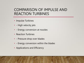
9. COMPARISON OF IMPULSE AND
REACTION TURBINES
• Impulse Turbines
• - High velocity jets
• - Energy conversion at nozzles
• Reaction Turbines
• - Pressure drop over blades
• - Energy conversion within the blades
• Applications and Efficiency
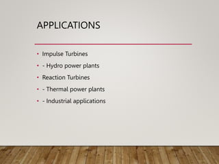