


More Related Content
Similar to Control Engineering for mechanical _lec2.pptx (20)
More from MdHelalHossain6 (20)


Recently uploaded (20)


Control Engineering for mechanical _lec2.pptx
- 1. Introduction to Hydraulics & Pneumatics Dr. Biplov Kumar Roy Assistant Professor (Mechanical Engineering) Dhaka University of Engineering & Technology DEGREE PROGRAM: B.Sc. in Mechanical Engineering COURSE CODE: ME 4401 COURSE TITLE: Control Engineering
- 2. Structure of a hydrostatic drive Aggregate Control elements Actuator Valves, determining the path, pressure, flow rate of the working fluid Elements doing work ŌĆó Linear ŌĆó Rotational ŌĆó Swinging Pump, motor Fluid reservoir Pressure relief valve Filter Piping
- 3. 2005/2006 I. Hydraulic and Pneumatic Systems 3 A typical hydraulic system 1 ŌĆō pump 2 ŌĆō oil tank 3 ŌĆō flow control valve 4 ŌĆō pressure relief valve 5 ŌĆō hydraulic cylinder 6 ŌĆō directional control valve 7 ŌĆō throttle valve
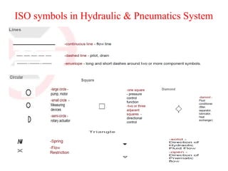
- 5. ISO symbols in Hydraulic & Pneumatics System
- 9. Pressure Control valve symbols Pilot-Operated Relief Valve Pressure-Reducing Valve Unloading Valve Sequence Valve Counterbalance valves
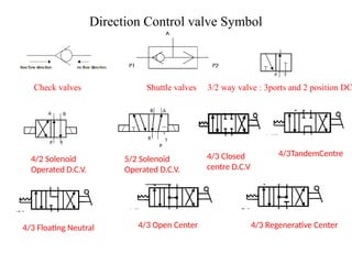
- 10. Direction Control valve Symbol Check valves Shuttle valves 3/2 way valve : 3ports and 2 position DC 5/2 Solenoid Operated D.C.V. 4/2 Solenoid Operated D.C.V. 4/3 Closed centre D.C.V 4/3TandemCentre 4/3 Floating Neutral 4/3 Open Center 4/3 Regenerative Center
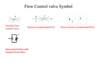
- 11. Flow Control valve Symbol Variable Flow Control Valve Pressure compensated F.C.V. Press. & temp. Compensated F.C.V. Flow control Valve with integral Check Valve
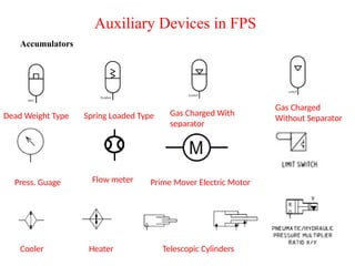
- 12. Auxiliary Devices in FPS Accumulators Dead Weight Type Spring Loaded Type Gas Charged With separator Gas Charged Without Separator Press. Guage Flow meter Prime Mover Electric Motor Cooler Heater Telescopic Cylinders